2-646 MACHINE OPERATIONS OPERACIONES DE MECANIZADO
15) As in step 7), confirm the center adjustment of
the tailstock. If necessary, repeat steps
8) to 14) to readjust.
16) Remove the lever type dial test indicators from
the mounting jig.
15) Como en el paso 7), verifique el ajuste del centro del
contrapunto. En caso necesario, realice los pasos
8) a 14) para reajustar.
16) Retire el indicador de prueba mediante un calibrador de
dial de la mordaza de instalación.
29-10-6 Headstock 2 Center Adjustment
Ajuste del centro del cabezal fijo 2
If the workpiece is damaged during transfer from the
headstock to headstock 2 due to centerline misalign-
ment, adjust the headstock 2 centering according to
the following procedure.
<Necessary Tools>
• Lever type dial test indicators
• Lever type dial test indicators mounting jig
• Hex wrench
• Hammer
• Rod
<Procedure>
1) Perform a zero point return of the X- and Z-axes
(Y-axis specifications: X/Z/Y-axes).
2) Open the operator door.
3) Using the manual pulse generator, move head-
stock 2 into an easily accessible position.
4) Turn OFF the main power.
5) Remove the 6 screws and remove the mainte-
nance cover.
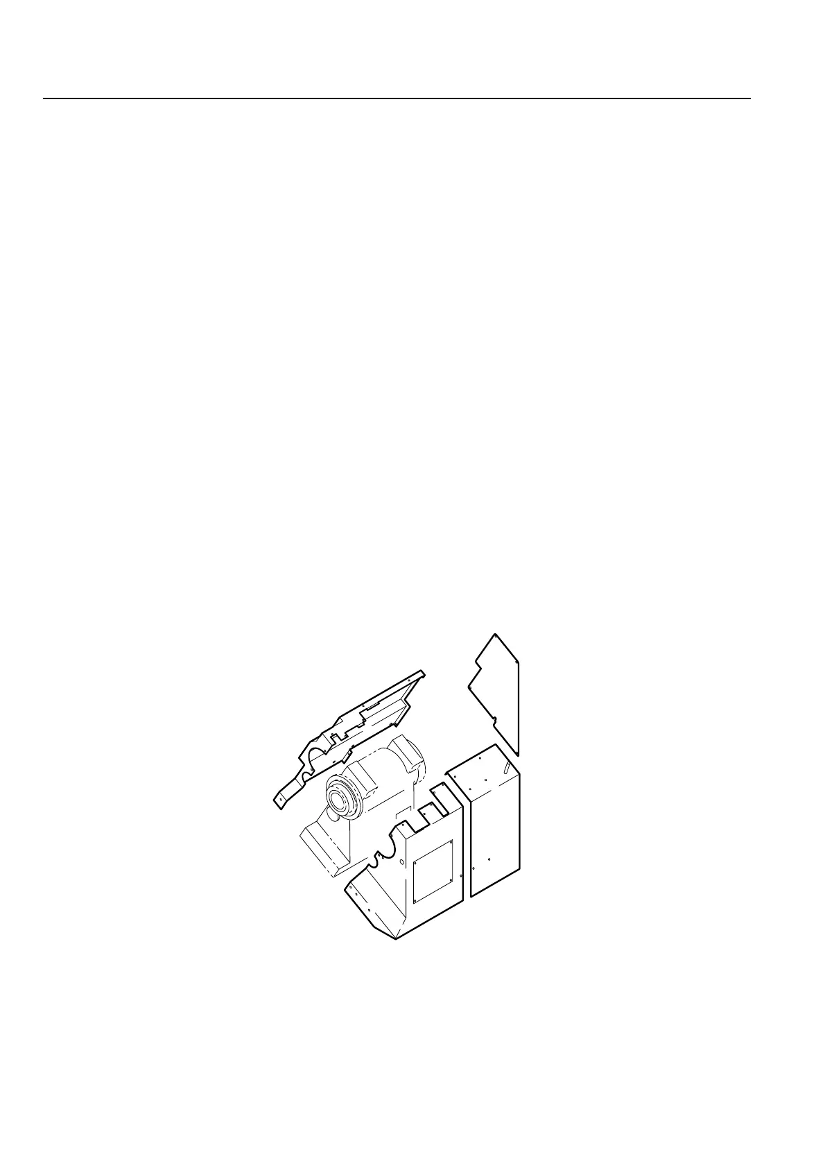
6) Remove the headstock 2 covers as shown in the
diagram below.
Si la pieza resulta deteriorada durante la transferencia desde
el cabezal fijo hasta el cabezal fijo 2 debido a un defecto de
alineación de la línea central, regule el centrado del cabezal
fijo 2 siguiendo el procedimiento que se indica a continuación.
<Herramientas necesarias>
• Indicadores de prueba mediante un calibrador de dial
• Mordaza de instalación de los indicadores de prueba
mediante un calibrador de dial
• Llave hexagonal
• Martillo
• Vástago
<Procedimiento>
1) Realice un retorno al punto cero de los ejes X y Z
(especificaciones del eje Y: ejes X/Z/Y).
2) Abra la puerta del operador.
3) Sirviéndose del generador manual de impulsos,
desplace el cabezal fijo 2 hasta una posición fácilmente
accesible.
4) DESCONECTE la alimentación principal.
5) Retire los 6 tornillos y la cubierta de mantenimiento.
6) Retire las cubiertas del cabezal fijo 2 tal y como se
muestra en el siguiente diagrama.
7) Turn ON the main power.
8) Clamp an appropriate sized workpiece in the
chuck and prepare a lever type dial test indica-
tors mounting jig of the dimensions shown in the
diagram below.
7) Conecte la alimentación principal.
8) Sujete una pieza de tamaño adecuado en el plato y
prepare una mordaza de instalación de los indicadores
de prueba mediante un calibrador de dial de las
dimensiones que se muestran en el siguiente diagrama.
 Loading...