2-486 MACHINE OPERATIONS OPERACIONES DE MECANIZADO
24-2 Using the Work Coordinate System
Utilización del sistema de coordenadas de pieza
When moving the headstock 2 (B-axis) by using the
work coordinate system, set the coordinate value of
the workpiece approach point at "B" of the work coor-
dinate system used for the workpiece transfer opera-
tion on the WORK OFFSET screen. Create a
program taking this point as "B0".
Set the workpiece approach point by using the fol-
lowing procedure.
1) Position the headstock 2 (B-axis) at the
workpiece transfer position manually.
2) Set the machine coordinate value indicated on
the CURRENT POSITION (ALL) screen as "B" in
the work coordinate system used for the work-
piece transfer operation on the WORK OFFSET
screen.
3) Return the headstock 2 (B-axis) to the zero point.
Cuando desplace el cabezal fijo 2 (eje B) utilizando el sistema
de coordenadas de pieza, establezca el valor de coordenadas
del punto de aproximación de pieza en "B" del sistema de
coordenadas de pieza utilizado en la operación de transferen-
cia de pieza en la pantalla CORRECCIÓN DE PIEZA. Cree
un programa tomando este punto como "B0".
Establezca el punto de aproximación de la pieza siguiendo el
procedimiento que le mostramos a continuación.
1) Posicione manualmente el cabezal fijo 2 (eje B) en la
posición de transferencia de piezas.
2) Copie el valor de coordenadas de la máquina que se
indica en la pantalla POSICIÓN ACTUAL (TODO) como
"B" en el sistema de coordenadas de pieza utilizado
para la operación de transferencia de pieza en la
pantalla CORRECCIÓN DE PIEZA.
3) Haga regresar el cabezal fijo 2 (eje B) al punto cero.
PRECAUCION
1. Do not set the workpiece transfer position as
"B" of "COMMON" on the WORK OFFSET
screen. If the workpiece transfer position is
set as "B" of "COMMON", the work coordi-
nate system called up in a program is shifted
by the set value, causing interference
between the tool, tool holder or turret and the
workpiece, chuck or fixture, which could
damage the machine.
2. When executing the zero return at the end of
the transfer process, always specify the
"G330" (headstock 2 reference point return)
command.
1. No defina la posición de transferencia de la pieza
como "B" de "COMÚN" en la pantalla CORRECCIÓN
DE PIEZA. En caso contrario, el sistema de coorde-
nadas de pieza llamado en un programa se
desplaza el valor establecido, lo que resultaría en
interferencias entre la herramienta, el soporte de
herramienta o la torreta y la pieza, plato o disposi-
tivo de fijación, hecho que podría causar desperfec-
tos en la máquina.
2. Cuando se ejecuta el retorno a cero al final del
proceso de transferencia, especifique siempre el
comando "G330" (retorno al punto de referencia del
cabezal fijo 2).
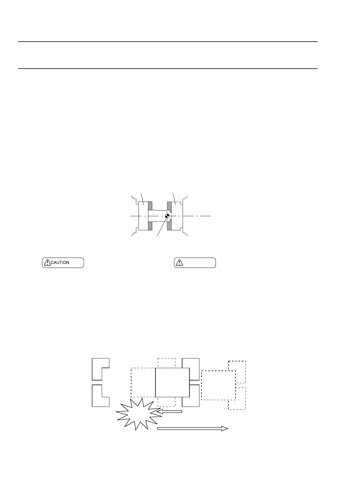
Spindle 1
Husillo 1
Spindle 2
Husillo 2
Workpiece Zero Point (G00 B0;)
Punto cero de la pieza (G00 B0;)
Interference
Interferencia
1) Motion to the Work Coordinate System Zero Point
(Rapid Traverse)
Movimiento hasta el punto cero del sistema de
coordenadas de pieza (avance rápido)
2) Motion to the Machine Zero Point
(Rapid Traverse)
Movimiento hacia el punt o cero de la máquina
(avance rápido)
 Loading...