2-270 MACHINE OPERATIONS OPERACIONES DE MECANIZADO
<Tool Nose Radius Offset Direction for Spindle 2> <Dirección de corrección del radio de la nariz de la
herramienta para el husillo 2>
15-2 Conditions for Use of the Automatic Tool Nose Radius Offset Function
Condiciones de uso de la función de corrección automática del radio de la nariz de la
herramienta
15-2-1 Imaginary Tool Tip Position
Posición de la punta de la herramienta imaginaria
To identify the point which is used for programming,
the term "imaginary tool tip position" is used.
It is necessary to set the code number (0 to 9) which
represents the imaginary tool tip position to the C
column displayed on the TOOL WEAR OFFSET
screen.
El término "posición de la punta de la herramienta imaginaria"
se emplea para identificar el punto que se utilizará para la pro-
gramación.
Será necesario ajustar el número de código (0 a 9) que repre-
senta la posición de la punta de la herramienta imaginaria en
la columna C que aparece en la pantalla CORRECCIÓN DES-
GASTE DE HRRTA.
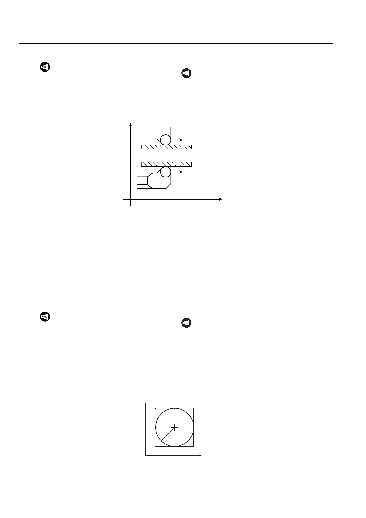
When using programs created for the spindle 1
on the spindle 2 side, pay careful attention to
the "+/−" direction of the Z-axis and the
direction of tool nose radius offset when
creating programs for such purposes since they
will be reversed.
NOT A
Cuando se utilizan programas creados para el husillo
1 sobre el lado del husillo 2, preste especial atención a
la dirección "+/−" del eje Z y a la dirección de la
corrección del radio de nariz de herramienta al crear
programas con tales fines dado que estos valores se
invierten.
G42
G41
+X
+Z
Tool Advancing Direction
Dirección de avance
de herramienta
Tool Advancing Direction
Dirección de avance
de herramienta
Workpiece
Pieza
1. The imaginary tool tip position, in refer-
ence to the center of the tool nose, is
determined according to the tool shape
and the tool mounting method in the turret
head. The imaginary tool tip position data
must be set in advance as with tool offset
data.
2. When G46 is used, set the imaginary tool
tip position with a number from 1 to 8.
NOT A
1. La posición de la punta de la herramienta imagi-
naria, se determina en referencia al centro de la
nariz de la herramienta de acuerdo con la forma
de la herramienta y con el método de instalación
de la herramienta en el cabezal de la torreta. Los
datos de la posición de la punta de la herramienta
imaginaria deberán ajustarse previamente como
datos de corrección de herramienta.
2. Cuando utilice G46, establezca la posición de la
punta de la herramienta imaginaria con un
número entre 1 y 8.
162
483
57
0
9
R
+Z
+X
0 to 9: Imaginary tool tip position
0 a 9: Posición de la punta de la herramienta imaginaria
 Loading...