1-45BASIC OVERVIEW INTRODUCCIÓN GENERAL
12 SETTING WORKPIECE ZERO POINT (Z0)
CONFIGURACIÓN DE PUNTO CERO DE PIEZA (Z0)
Set the distance between the tentative workpiece
zero point and the actual workpiece zero point on the
WORK OFFSET screen.
Configure la distancia entre el punto cero de la pieza provisio-
nal y el punto cero de la pieza real en la pantalla
CORREC.PIEZA.
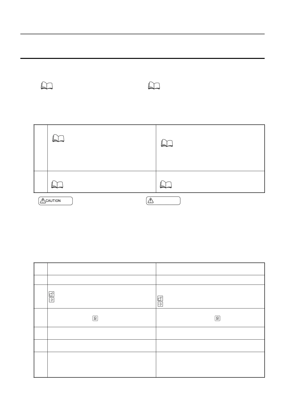
<Before Setting> <Antes de realizar la configuración>
<Setting the Workpiece Zero Point> <Ajuste del punto cero de la pieza>
For the relationship between the work
coordinate system and tools or tool preset-
ter, refer to "TOOL PRESETTER, TOOLS
AND WORK COORDINATE SYSTEM"
(page 1-42).
Para mayor información acerca de la relación entre
el sistema de coordenadas de pieza y el preajusta-
dor de herramienta o las herramientas, consulte
"PREAJUSTADOR DE LA HERRAMIENTA,
HERRAMIENTAS Y SISTEMA DE COORDENA-
DAS DE PIEZA" (página 1-42).
1.
Set the tool geometry offset data. Configure los datos de corrección geométrica de la
herramienta.
2.
Clamp a workpiece, and adjust the chucking pressure. Bloquee una pieza y ajuste la presión de agarre.
PRECAUCION
Set "0" at "COMMON Z" on the WORK OFFSET
screen. If a value is set for "COMMON Z", the
coordinate system is shifted in the same direction
regardless of the spindle to be used for
machining, resulting in interference.
[Interference of the tool, tool holder or turret head
with the workpiece, chuck or fixture, Machine
damage]
Establezca el valor "0" en "COMÚN Z" en la pantalla
CORRECIÓN DE PIEZA. Si se asigna un valor para
"COMÚN Z", el sistema de coordenadas se desplaza en
la misma dirección sin importar el husillo empleado
para el mecanizado, lo que provoca interferencias.
[Interferencia de la herramienta, el soporte de
herramienta o el cabezal de la torreta con la pieza, plato
o dispositivo de fijación, desperfectos en la máquina]
"TOOL GEOMETRY OFFSET VALUE
MEASUREMENT/ENTRY WITH MANUAL
IN-MACHINE TOOL PRESETTER" (page
1-37)
"MEDICIÓN DEL VALOR DE CORREC-
CIÓN DE GEOMETRÍA DE LA HERRA-
MIENTA/ENTRADA CON
PREAJUSTADOR DE HERRAMIENTA
MANUAL INTEGRADO A LA MÁQUINA"
(página 1-37)
"CHUCKING" (page 1-47) "SUJECIÓN" (página 1-47)
1.
Set the door interlock key-switch in the [NORMAL]
position.
Ponga el conmutador con llave de interbloqueo de
puerta en la posición [NORMAL].
2.
Close the door. Cierre la puerta.
3.
Turn the operation selection key-switch to
[Operation Enable] or
[Operation & Edit Enable].
Gire el conmutador con llave de selección de
funcionamiento a la posición
[Operación activada] o
[Operación & Edición activadas].
4.
Display the WORK OFFSET screen.
Function selection key (OFFSET)
→ [WORK OFFSET]
Visualice la pantalla CORRECCIÓN DE PIEZA.
Tecla de selección de función (OFFSET)
→ [CORREC. PIEZA]
5.
Move the turret to the position free from any interfere
when the turret head is rotated.
Desplace la torreta a una posición libre de
interferencias al girar el cabezal de la torreta.
6.
Index manually the cutting tool that allows facing. Indice manualmente la herramienta de corte que
permite la realización del refrentado.
7.
Move the tool close to the workpiece end face "Z0"
position using a manual operation mode while
observing the clearance between the workpiece and
the tool through the door window.
Aproxime la herramienta a la posición "Z0" de la
superficie del extremo de la pieza mediante un modo
de funcionamiento manual, controlando siempre la
distancia entre dicha pieza y la herramienta a través de
la ventana de la puerta.
 Loading...