2-331MACHINE OPERATIONS OPERACIONES DE MECANIZADO
17 CUTTER RADIUS OFFSET
CORRECCIÓN DEL RADIO DEL CORTADOR
The cutter radius offset means shifting of the tool
paths to the right or left by the radius from the pro-
grammed paths.
Generally, when cutting a pocket or carrying out con-
touring operation using an end mill, the cutter radius
offset function is used to finish the workpiece in the
shape specified in the drawing.
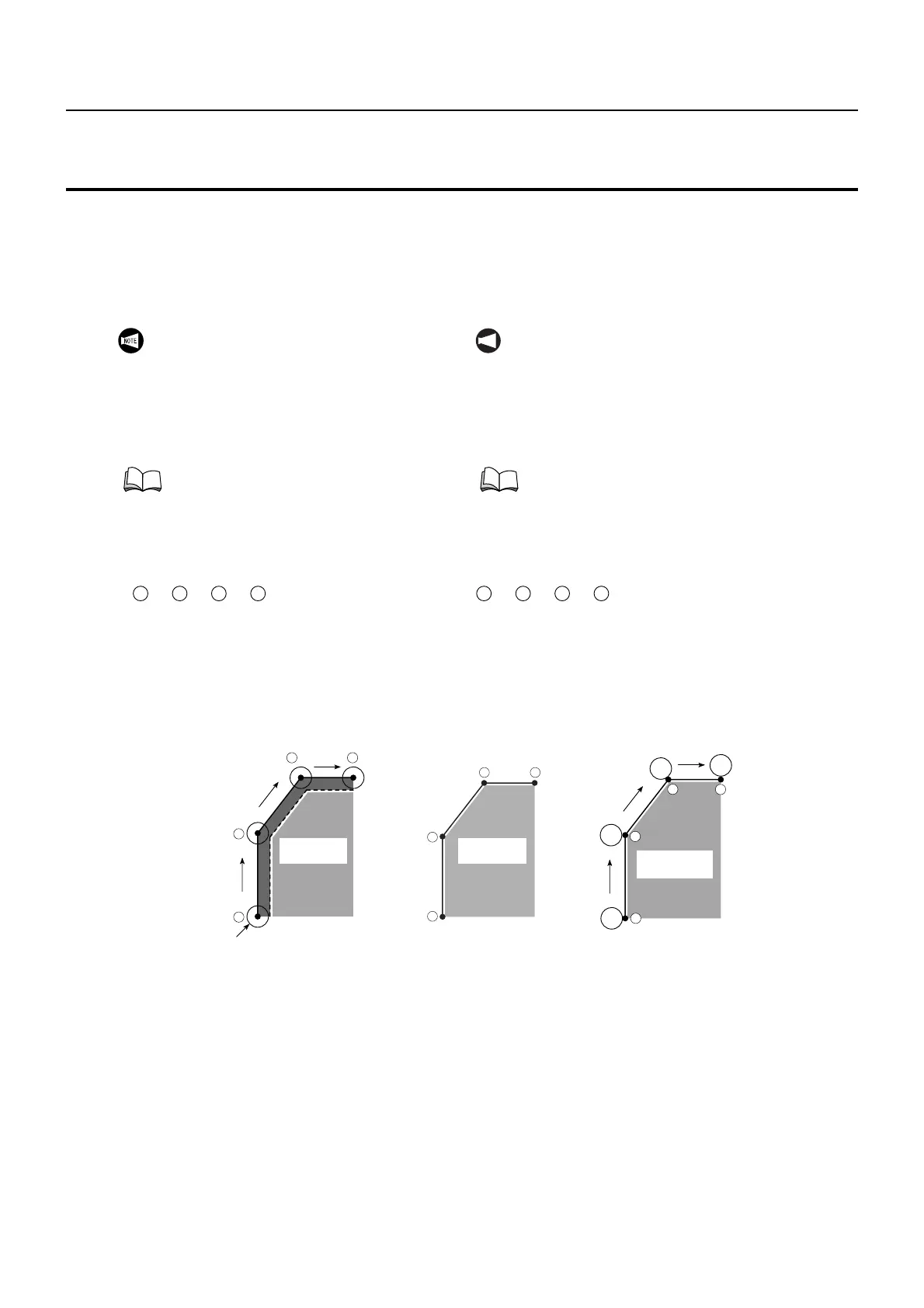
How the shape in Fig. 1 is finished using the cutter
radius offset function is briefly explained below.
Specify the required shape to be finished in the pro-
gram:
→ → →
Since the center of a cutting tool moves along the
defined paths, the cutting tool moves along the paths
shown in Fig. 1 if the program is created without
using the cutter radius offset function.
The workpiece is finished to the shape indicated by
the broken line, which is smaller than the shape
required by the radius of the cutting tool.
La corrección del radio del cortador significa desplazar las tra-
yectorias de la herramienta a la derecha o a la izquierda
mediante el radio de las trayectorias programadas.
Generalmente, al cortar una cavidad o realizar una operación
de contorneado con una fresa extrema, la función de correc-
ción del radio del cortador se utiliza para finalizar la pieza con
la forma especificada en el plano.
A continuación se explica brevemente cómo se acaba la
forma de la Fig. 1 usando la función de corrección del radio
del cortador.
Especifique la forma que se requiera acabar en el programa:
→ → →
Dado que el centro de una herramienta de corte se despla-
zará a lo largo de las trayectorias definidas, la herramienta de
corte se desplazará a lo largo de las trayectorias mostradas
en la Fig. 1 si se crea el programa sin utilizar la función de
corrección del radio del cortador.
La pieza se acabará con la forma indicada mediante la línea
discontinua, la cual será de menor tamaño que la forma
requerida por el radio de la herramienta de corte.
To shift the tool paths from the programmed paths,
input the radius of the cutting tool as the cutter radius
offset data to the TOOL GEOMETRY OFFSET
screen.
If the cutter radius offset function is used, the tool
paths are shifted outside from the programmed paths
by the input offset amount as shown in Fig. 3 to finish
the required shape.
In this manner, by shifting the tool paths from the pro-
grammed paths by using the cutter radius offset
function, it is not necessary to obtain the coordinate
values using complicated calculation to generate the
tool paths to finish the workpiece to the required
shape.
Para desplazar las trayectorias de herramienta desde las tra-
yectorias programadas, introduzca el radio de la herramienta
de corte como datos de corrección del radio del cortador en la
pantalla CORRECCIÓN GEOMETRÍA DE HRRTA.
Si se utiliza la función de corrección del radio del cortador, las
trayectorias de la herramienta se desplazarán fuera de las tra-
yectorias programadas mediante la cantidad de corrección de
entrada mostrada en la Fig. 3 para acabar la forma requerida.
De este modo, al desplazar las trayectorias de herramienta a
partir de las trayectorias programadas usando la función de
corrección del radio del cortador, no será necesario obtener
los valores de coordenadas usando cálculos complicados
para generar las trayectorias de herramienta para acabar la
pieza a la forma requerida.
Since there are a number of tool patterns which
will be used for actual machining and they will
differ among users, it is not possible to explain
all of the tool patterns in this manual. The
explanation given in this chapter is
concentrated on the basic programming so that
the readers will be able to acquire basic
knowledge of the cutter radius offset function.
For more details, please refer to the instruc-
tion manuals supplied by the NC unit manu-
facturer.
1 2 3 4
NOT A
Dado que existen varios patrones de herramienta que
se utilizarán para el mecanizado real y que no son
iguales para todos los usuarios, en este manual no se
pueden explicar todos los patrones de herramienta.
La explicación ofrecida en este capítulo se concentra
en la programación básica de modo que los lectores
sean capaces de adquirir los conocimientos básicos
de la función de corrección del radio del cortador.
Para obtener más información, consulte los
manuales de instrucciones suministrados por el
fabricante de la unidad de CN.
1 2 3 4
1
2
3
4
Fig. 1
Fig. 1
Tool
Herramienta
Workpiece
Pieza
1
2
3
4
Fig. 3
Fig. 3
Workpiece
Pieza
1
2
3
4
Workpiece
Pieza
Fig. 2
Fig. 2
 Loading...