Page 7-27
Troubleshooting
INTER-TEL
®
AXXESS
®
MANUAL VERSION 11.0 – May 2008
System Issues
7
TROUBLE-
SHOOTING
A. SYSTEM ISSUES
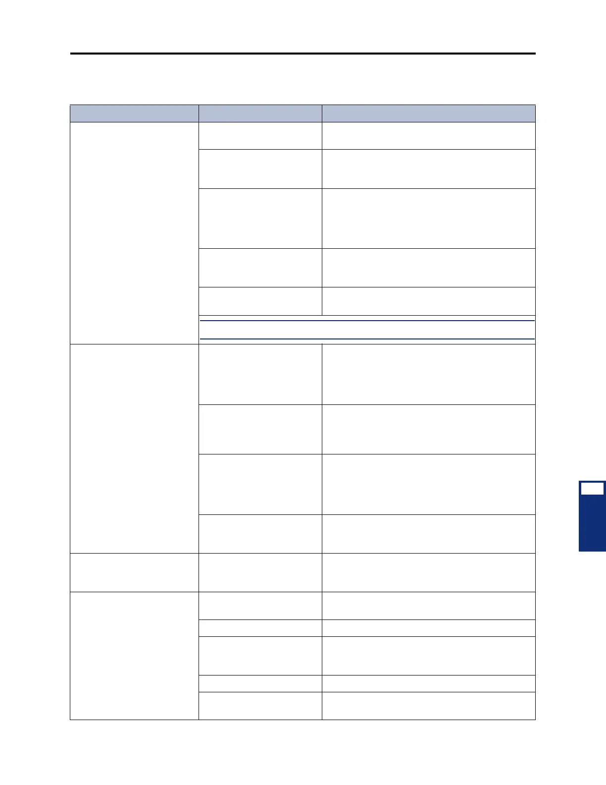
Table 7-6. System Troubleshooting Chart
Symptom Possible Cause Corrective Action
Repeated occurrence of all
calls in progress dropping
AC line is not isolated and
dedicated
Have isolated, dedicated line installed. See page 3-
10 in INSTALLATION for details.
Defective power supply See INSTALLATION, page 3-83 or 3-92, to perform
the power supply electrical test. Replace the power
supply if faulty.
Equipment chassis located
near a strong magnetic field
or other potential source of
interference (copy machines,
power transformer, etc.)
Relocate the equipment chassis a minimum of 20
feet (6 meters) from any equipment that is a poten-
tial source of interference.
IC-CO/CO-CO Disconnect
timer(s) need(s) adjustment
See dialed digits field in SMDR, page 5-311 in FEA-
TURES. Set timer(s) to a higher value. See PRO-
GRAMMING, page 6-329.
Defective CPC or CPU Card See page 7-3 for LED and system voltage informa-
tion. Replace the card if faulty.
NOTE: The central office must provide a minimum of 18mA loop current
All phones in the system are
inoperative; no LED indication
when a trunk or call button is
pressed; +24V measurement
is not present
Open or loose connection in
the cable between the power
supply and the chassis back-
plane, or a defective cable
Turn off the AC power. Check to see that the back-
plane-to-power supply interface cable is properly
connected. Repair or replace the power supply, the
cable, and/or the backplane if the connection is
faulty.
Defective power supply or
connector
Use a voltmeter to check the +24VDC voltage on
the chassis backplane or power supply. If the volt
age is not +24VDC ±5%, replace the power sup ply
and/or the cable.
Defective keyset card Remove all keyset cards from the chassis. Replace
the cards one at a time and check the system volt-
ages on the chassis backplane or power supply
(see page 7-3), until the defective card is isolated.
Replace the faulty card.
Defective chassis backplane Check the system voltages on the chassis back-
plane (see page 7-3). Replace the chassis assem-
bly or the chassis backplane if necessary.
Database restore aborts
before finishing
PC's power saver feature
shuts down the PC and sev-
ers the communications link
Disable the PC's power saver feature.
DISA inoperative User error See FEATURES, page 5-118, for correct proce-
dures.
Telephone not compatible User must dial in from a DTMF telephone.
Programming error Ensure that the trunk group is identified correctly as
a day or night DISA trunk group. See PROGRAM-
MING, page 6-228.
Defective trunk card Replace the associated card.
Defective CPC or CPU Card See page 7-3 for LED and system voltage informa-
tion. Replace the card if faulty.