Page 3-33
Installation
INTER-TEL
®
AXXESS
®
MANUAL VERSION 11.0 – May 2008
T1/PRI Trunk Terminations from RJ-Type Blocks
INSTALLATION
3
7.18 Install the T1/PRI trunks as outlined in the following steps. See Figure 3-15 below for a
diagram of the complete layout.
1. On the MDF backboard, mount one eight-conductor modular jack assembly for each
T1/PRI trunk termination on the telephone company RJ-type block(s).
2. Connect T1 cable between the telephone company terminations and the corresponding
modular jack assemblies as follows:
NOTE: If the telephone company termination is more than 2000 feet (600 meters)
from the MDF, special T1 cable must be used (see page 2-54 for cable specifications).
For shorter distances, two lengths of standard two-pair voice-frequency cable (one
cable for transmit and one cable for receive) may be used instead.
a.
Terminate one end of a six-pair cable on each modular jack assembly. See Figure
3-14 on the previous page.
b. Terminate the other end of the six-pair cable on the right side of the T1/PRI RJ-
type terminal block.
3. Plug one end of a four-pair, non-reversing (straight through), mod-to-mod line cord into
each modular jack assembly (mounted in step 1). The other end of each line cord is
later plugged into the T1 jack on the corresponding T1 or T1/E1/PRI card
NOTE: Make sure the connectors on the ends of each line cord are properly attached.
If any of the wires are cracked or broken, T1/PRI transmission problems can occur.
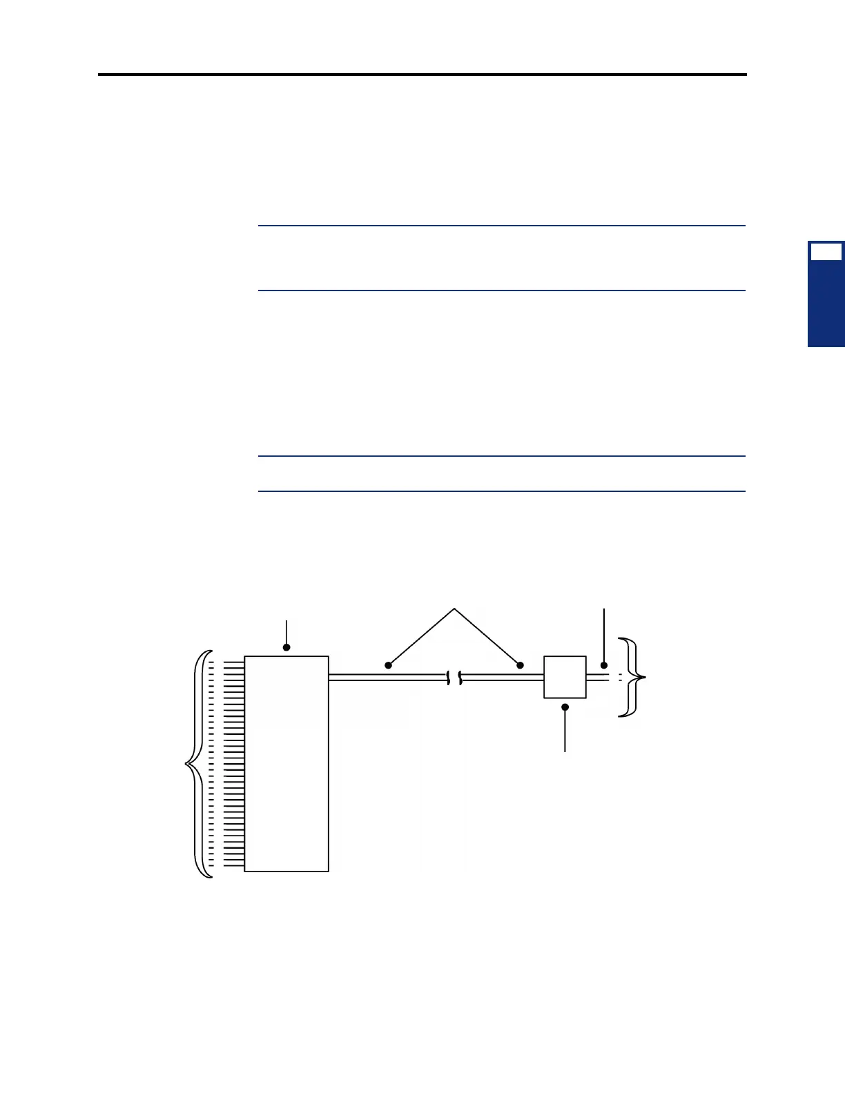
Figure 3-15. T1/PRI Trunk Terminations from RJ-Type Blocks
RJ-TYPE
BLOCK
T1 CABLE
FOUR-PAIR,
NON-REVERSING,
MOD-TO-MOD
LINE CORD
EIGHT-CONDUCTOR
MODULAR JACK ASSEMBLY
TO
TELCO
TO
T1 CARD