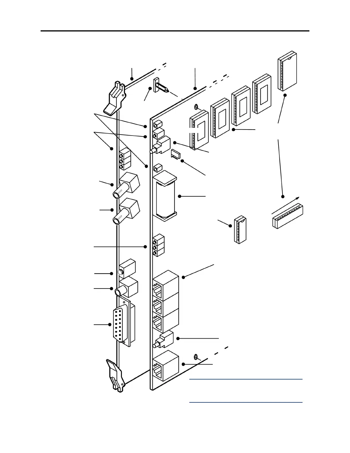
Figure 3-51. PCM-F Card and Attached CPU020-Q Card
PCM-F CARD
BATTERY
CHECK SWITCH
BATTERY BACK-UP
(BBU) STRAP
LED
INDICATORS
BATTERY
TEST POINTS
DB15 PCM
CONNECTOR
RESET
SWITCH
RS232
CONNECTORS
U25
U41
U13
RELAY JACK
FEATURE-UNIT
PAL
LED
INDICATORS
EXTERNAL
PAGING PORT
CPU ACTIVE (GREEN)
DATABASE ERROR (RED)
MINOR ALARM (YELLOW)
LITHIUM BATTERY
“Q” SOFTWARE
COMPONENTS
U41 is at the far edge of the card
STANDOFF
FIBER RECEIVE
JACK
FIBER TRANSMIT
JACK
NOTE: For purposes of detail, this drawing does
not show the EMI shield attached to the front
edge of the card.
MUSIC JACK
CPU020-D CARD
TO VOICE PROCESSING PC
AUDIO INTERFACE CARD (AIC)
CPU SERIAL PORT 1
CPU SERIAL PORT 2
CPU SERIAL PORT 3
EXT. CLOCK ACTIVE (GREEN)
REMOTE SYNC (GREEN)
LOCAL SYNC (GREEN)
TP1 (VBAT+)
BATTERY OFF (RED)
ON
OFF
TP2 (VBAT-)
U4
U5
U6
U7
TO FIBER TRANSMIT JACK ON
OTHER PCM-F CARD
TO FIBER RECEIVE JACK ON
OTHER PCM-F CARD
A/MU LAW
SWITCH