Page 7-11
Troubleshooting
INTER-TEL
®
AXXESS
®
MANUAL VERSION 11.0 – May 2008
ATM Switch LEDs
7
TROUBLE-
SHOOTING
B. ATM SWITCH LEDS
3.3 Each ATM switch type has LEDs that indicate the status of the Switch and of individual
ports.
ForeRunner LE155
3.4 The ForeRunner LE155 switch has several LEDs. S1 indicates the software status; S2,
the power status; and the port LEDs, the port status. These LEDs will light (or blink) a differ-
ent color depending on the current status, as described in the following table.
NOTE: If the expansion slot is populated, each additional port will also have individual LEDs.
ASX-200BX
3.5 The following table describes the LEDs available on the ASX-200BX switch.
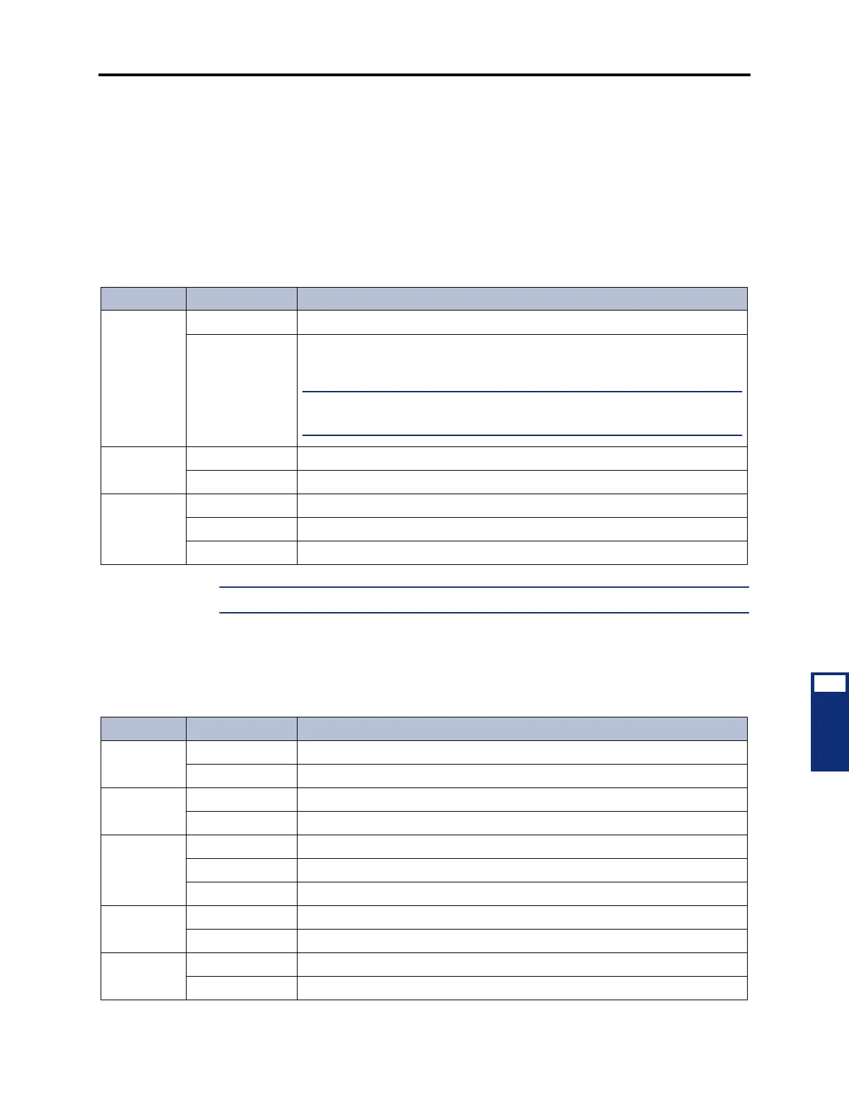
Table 7-3. ForeRunner LE155 ATM Switch LEDs
LED Color Indication
S1 Green (solid) The switch software is functioning properly.
Red (blinking) The switch software is currently booting. This LED will change to green once
the Switch is finished booting.
NOTE: If this LED continues to blink red, even after a reboot, the SRAM is
corrupt. Contact Inter-Tel
®
for additional assistance.
S2 Green (solid) The switch has power.
Unlit The switch does not have power.
Port (e.g.,
A1, C3, etc.)
Green (blinking) The port is receiving packets.
Red (solid) The port is not communicating.
Yellow (blinking) There is a port alarm.
Table 7-4. ASX-200BX ATM Switch LEDs
LED Color Indication
ACT Amber (solid) The Ethernet port is transmitting and receiving data.
Unlit If unlit, the connection has experienced a collision or there is no activity.
L1 Green (solid) The Ethernet connection is active.
Unlit There is no active Ethernet connection.
PWR Green (solid) The Switch Control Processor (SCP) is functioning properly.
Red (solid) The SCP is resetting.
Unlit There is no power to the SCP.
5 Volts Green (solid) The power supply is functioning.
Red (solid) There is a problem with the power supply.
RXn Green (solid) The port is receiving data from the phone system.
Red (solid) There is no connection or no data is being received.