Page 3-85
Installation
INTER-TEL
®
AXXESS
®
MANUAL VERSION 11.0 – May 2008
Wall Mount the Chassis, if Desired
INSTALLATION
3
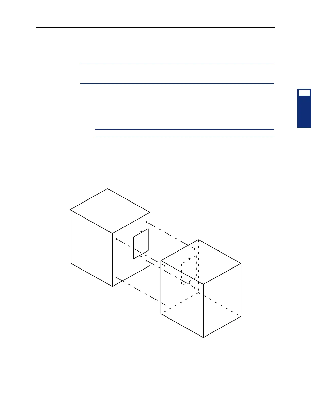
E. WALL MOUNT THE CHASSIS, IF DESIRED
9.6 The basic or expanded chassis may be mounted on the MDF backboard as outlined in
the following steps.
NOTE: If the two portions of a tri-/quad-chassis system are installed on the same vertical plane
on the same MDF, the first (master) pair of chassis must be separated from the second (slave)
pair of chassis by at least one foot to provide proper air circulation.
1.
With the front cover removed, position the chassis on the MDF backboard and mark the
location of the top two mounting screw holes. (Be sure to allow sufficient air circulation
around the chassis.) Set the chassis aside.
2. Drive a screw into the center of each mounting hole marking, allowing the heads of the
screws to protrude slightly.
NOTE: Use screws of sufficient strength to support the equipment chassis.
3.
Hang the chassis on the two screws. If necessary, adjust the screws to ensure the chassis
is held firmly in place.
4. To further secure the chassis to the backboard, insert screws into the bottom two mount-
ing holes from inside the chassis.
Figure 3-42. Connecting Two Equipment Chassis Together