Page 7-42
Troubleshooting
INTER-TEL
®
AXXESS
®
MANUAL VERSION 11.0 – May 2008
Phone Issues
G. PHONE ISSUES
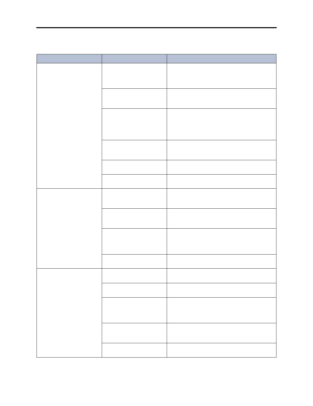
Table 7-12. Phone Troubleshooting Chart
Symptom Possible Cause Corrective Action
Phone inoperative; LED indi-
cation present while any but-
ton with an LED is held
down; reorder tone is heard
when button is pressed
Programming error (circuit
identified as dual single-line
sets (SLA); no reorder tone is
heard)
Identify the circuit for phone use, not dual single-
line sets (SLA). See page 6-118 in PROGRAM-
MING.
System lockout caused by
excessive data errors (dis-
plays SYSTEM LOCKOUT)
Remove and replace the line cord to reset the
phone.
Defective cabling or connec-
tions
Ensure that all cables are correctly connected to
the modular jack as shown in Figure 3-1 on
page 3-19 in INSTALLATION. Check for loose or
open connections in the station cabling and the line
cord.
Defective phone Perform the keyset self-test as described in
INSTALLATION, page 3-182, and replace the
phone if faulty.
Defective DKSC, EKSC, or
AKSC
Replace the associated DKSC, EKSC, or AKSC.
Defective CPC or CPU Card See page 7-3 for LED and system voltage informa-
tion. Replace the card if faulty.
Phone inoperative; no LED
indication when any button is
pressed; no audio is present
Open or defective thermistor
on the associated DKSC,
EKSC, or AKSC
If a short causes a thermistor to open, it automati-
cally closes when the short is removed. Replace
DKSC, EKSC, or AKSC if the thermistor is faulty.
Defective phone Perform the keyset self-test as described in
INSTALLATION, page 3-182, and replace the
phone if faulty.
Defective cabling or connec-
tions
Ensure that 24VDC is present at the modular jack
and polarity is correct. Check for loose or open
connections in the station cabling and the line cord.
See Figure 3-1 on page 3-19 in INSTALLATION.
Defective DKSC, EKSC, or
AKSC
Replace the associated DKSC, EKSC, or AKSC.
Erratic phone operation (lamp
status incorrect)
Station cable exposed to
interference
Ensure proper station cable runs. See INSTALLA-
TION, page 3-16.
Station loop limits exceeded Perform the station loop resistance test as out lined
on page 3-69 in INSTALLATION.
Defective cabling or connec-
tions
Ensure that 24VDC is present at the modular jack
and polarity is correct. Check for loose or open
connections in the station cabling and the line cord.
See Figure 3-1 on page 3-19 in INSTALLATION.
Defective phone Perform the keyset self-test as described in
INSTALLATION, page 3-182, and replace the
phone if faulty.
Programming error Ensure that the proper keymap has been assigned
to the phone. See PROGRAMMING,
page 6-306.