Installation
INTER-TEL
®
AXXESS
®
MANUAL VERSION 11.0 – May 2008
Page
3-70
Connecting Two T1 or E1 Cards
G. CONNECTING TWO T1 OR E1 CARDS
7.54 T1, E1/PRI or T1/E1/PRI cards are used for connecting system nodes in a network.
Each network span requires two T1, E1/PRI, or T1/E1/PRI cards, one for each end of the span.
The cards require the most recent firmware to support networking – use upgrade kit part num-
ber 828.1506 [SW206 in Europe]. Point-to-point clear channel T1 spans are used to connect
the nodes. For each network span, order a clear channel, point-to-point T1 or E1 span from the
service provider (not PRI service, even though you are using T1, E1/PRI, or T1/E1/PRI cards).
7.55 T1 Cards can be used to connect two non-networking telephone systems together using
customer-provided cable. The systems may be located in separate buildings and the cabling
between them may be as long as 6000 feet (1800 m), without repeaters.
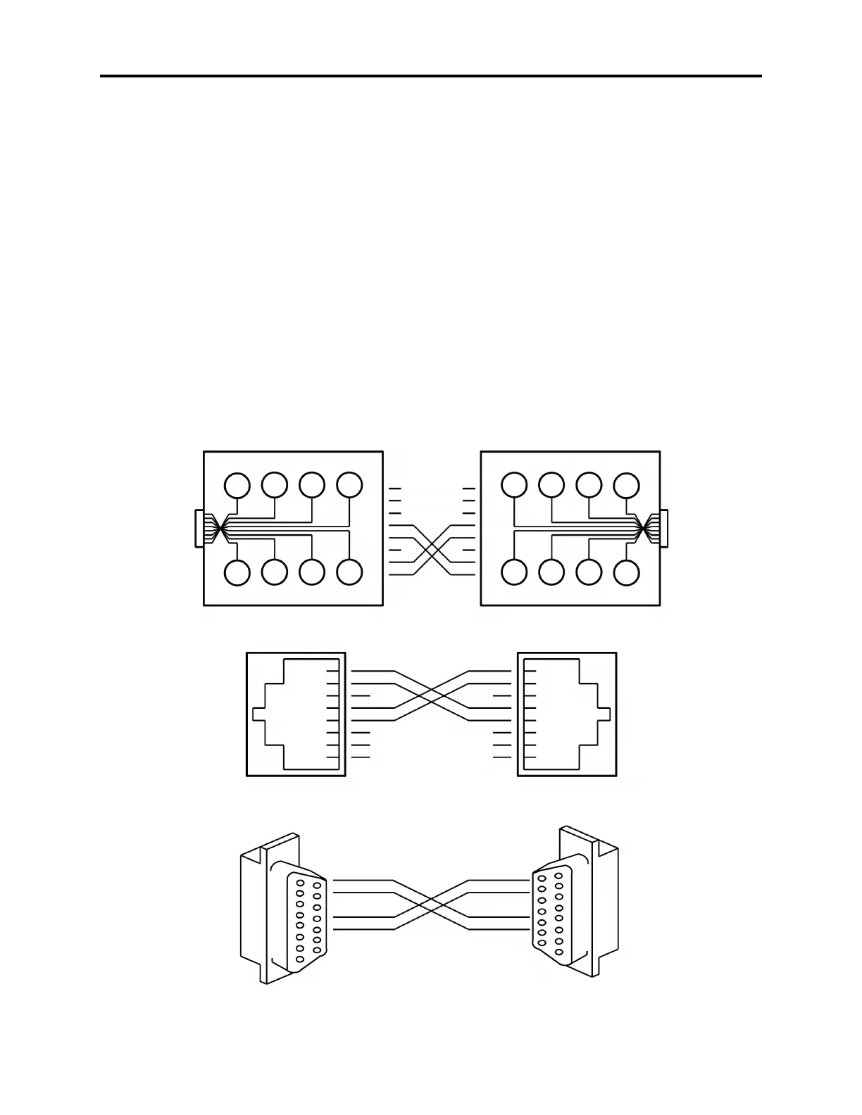
7.56 When connecting two systems together, the line cord (or cabling) between the two T1
Cards must be wired so that the receive pair (tip 1 in and ring 1 in) on each card is connected to
the transmit pair (tip out and ring out) on the other card, as shown in the figure below. (For
information on programming various types of T1 or E1 installations, see page 6-126.)
Figure 3-34. Connecting Two T1 Cards Together
MODULAR JACK ASSEMBLY
TO
T1 CARD
T1 CARD
RJ48C JACK
T1 CARD
RJ48C JACK
T1 CARD
DB 15
CONNECTOR
T1 CARD
DB 15
CONNECTOR
S
BR
Y
G
BL
O
BK
R
1
3
5
7
2
4
6
8
1
2
3
4
TIP
(OUT)
RING 1
(IN)
RING
(OUT)
TIP 1
(IN)
8
7
6
5
4
3
2
1
T
R
T1
R1
1
2
3
4
5
6
7
8
R1
T1
R
T
OR
OR
1 Tip (Out)
9 Ring (Out)
3 Tip 1 (In)
11 Ring 1 (In)
Tip (Out) 1
Ring (Out) 9
Tip 1 (In) 3
Ring 1 (In) 11
8
7
6
5
4
3
2
1
T
R
T1
R1
TO
T1 CARD
1
3
5
7
2
4
6
8
MODULAR JACK ASSEMBLY
TIP 1
(IN)
RING 1
(IN)
RING
(OUT)
TIP
(OUT)
4
3
2
1
G
Y
BR
S
R
BK
O
BL
8
7
6
5
5
6
7
8
1
2
3
4
5
6
7
8
R1
T1
R
T