Page 3-103
Installation
INTER-TEL
®
AXXESS
®
MANUAL VERSION 11.0 – May 2008
Installing CPU020/PCM or CPU020/PCMA Cards
INSTALLATION
3
NOTE: The FIBER TRANSMIT jack on each card must be connected to the FIBER
RECEIVE jack on the other card. A 8.5-foot (2.5 m) cable is available using part no.
813.1628 [C118 in Europe]. Or, if necessary, contact Inter-Tel's CommSource division or
Inter-Tel Europe for information on purchasing longer cable lengths. Custom cables can
also be built using industry-standard ST-type connectors.
5. For CPU020-A/PCMA cards only: Connect the fibre-optic or CAT5 cable between the
PCMA card and the ATM Switch. If installing multiple chassis, make sure you connect
them to different interfaces on the ATM Switch (see page 2-9 for details).
6. Turn ON the AC POWER switch and observe the LEDs on the front edge of the card
for the indications below. If installing an ATM system, turn ON the power to the ATM
Switch. If the LEDs are incorrect, recheck the system voltages as outlined on page 3-
92, and then contact Customer Support.
CPU020-D/PCM-D: See Figure 3-50 on page 3-107 for LED indicator locations.
CPU020-Q/PCM-F:
See Figure 3-51 on page 3-108 for LED indicator locations.
CPU020-X/PCM-F:
See Figure 3-52 on page 3-109 for LED indicator locations.
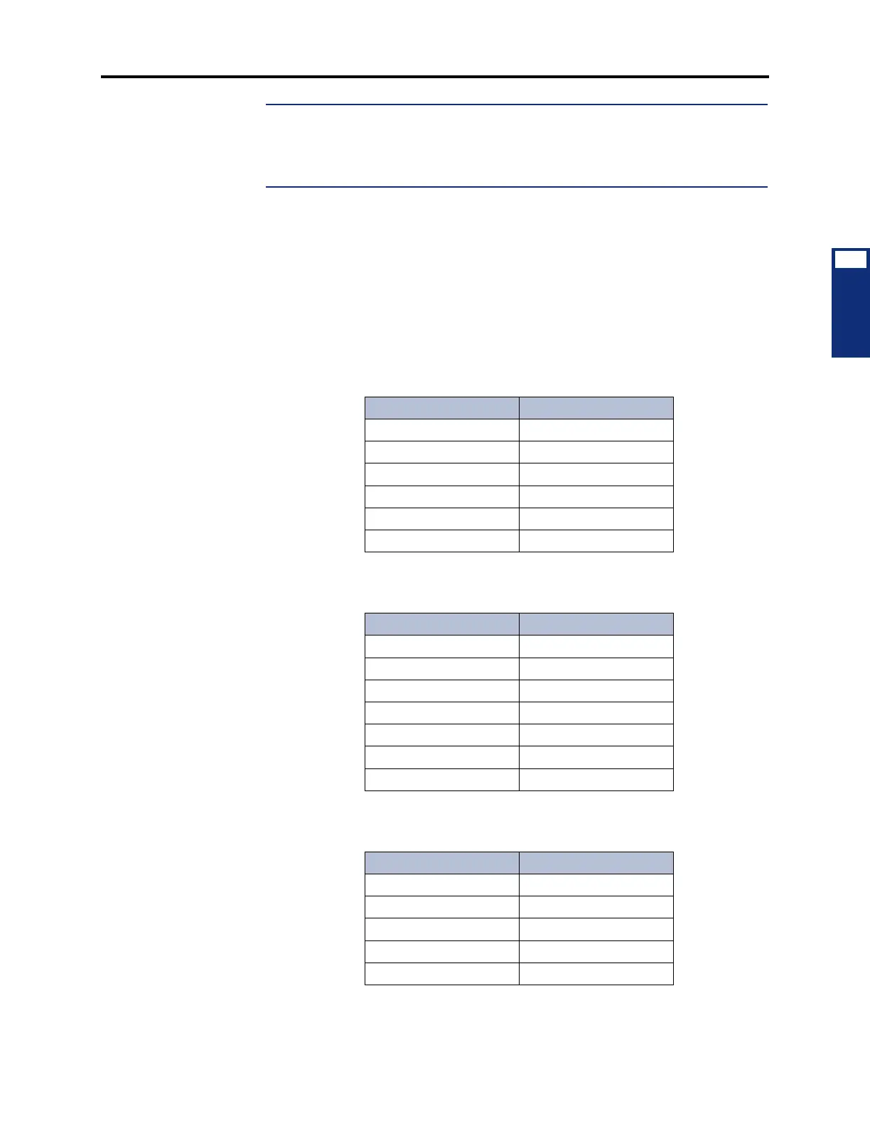
Table 3-13. CPU020-D/PCM-D LED Indications
Name Correct Indication
Battery Off Off (Red)
CPU Active Lit (Green)
Database Error Off* (Red)
Minor Alarm Off* (Yellow)
External Clock Active Off (Green)
Local Synch Off (Green)
Table 3-14. CPU020-Q/PCM-F LED Indications
Name Correct Indication
Battery Off Off (Red)
CPU Active Lit (Green)
Database Error Off* (Red)
Minor Alarm Off* (Yellow)
External Clock Active Off (Green)
Remote Synch Off (Green)
Local Synch Off (Green)
Table 3-15. CPU020-X/PCM-F LED Indications
Name Correct Indication
CPU Active Lit (Green)
Minor Alarm Off* (Yellow)
External Clock Active Off (Green)
Remote Synch Off (Green)
Local Synch Off (Green)