Installation
INTER-TEL
®
AXXESS
®
MANUAL VERSION 11.0 – May 2008
Page
3-134
BRS Ports Programmed as Station Ports
BRS Ports Programmed as Station Ports
10.57 The following is an example of the termination between a BRS (S/T) station port and a
BRI ISDN (S/T) device using four-wire connection.
• The BRS ports are programmed or equipped as station ports. The station ports are con-
nected to an ISDN device that has an S/T interface, such as ISDN telephone or video
conferencing device.
NOTE: The device must have an S/T interface to work with the BRS card.
• A BRS port is programmed or equipped as a station port that provides dial tone to the
other ISDN device (BRI station to BRI trunk) using an S/T interface
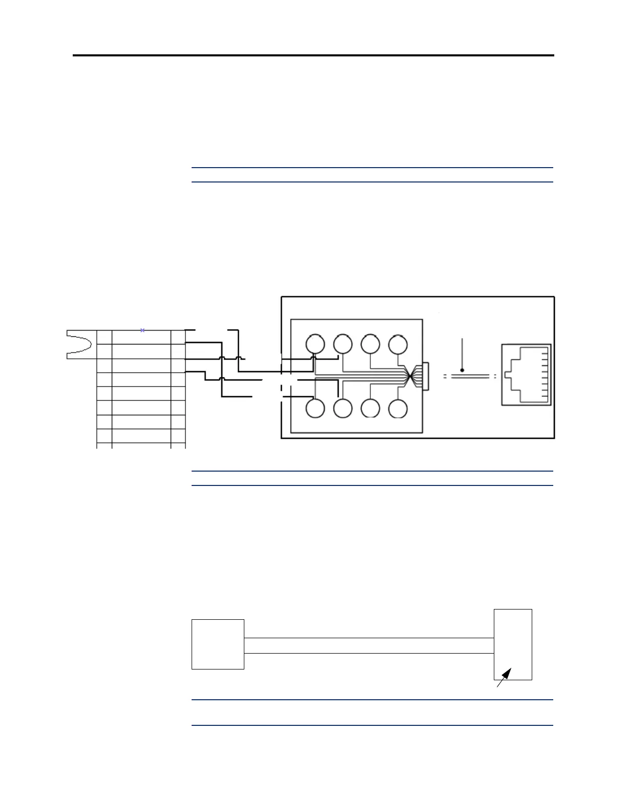
Figure 3-66. BRS Station/Station Port to a BRI ISDN Device.
NOTE: See page 3-38 for more information on the BRS card connection.
BRU Ports Programmed as Trunk Ports
10.58 The following is an example of the termination between a BRU (U) trunk port and an
incoming BRI circuit from the Central Office. The BRU ports are programmed or equipped as
trunk ports that connect to the incoming BRI circuit from the Central Office or ISDN provider.
Figure 3-67. BRU Trunk/Trunk Port to CO
NOTE: BRI U interface is not polarity sensitive. BRU card has a built-in NT1 on each
port. Therefore, an external NT1 is not required.
MDF to 8-Pin RJ45 Modular Jack for the BRS Ports
TXP0(R)
RXP0(R1)
RXN0(T1)
TXN0(T)
MODULAR JACK ASSEMBLY
66M50
TIP
(OUT)
TIP1
(IN)
RING
(OUT)
RING1
(IN)
5
6
7
8
4
3
2
1
1
3
5
7
2
4
6
8
1
2
3
4
5
6
7
8
T
T1
R1
R
4-Pair,
Non-reversing
MOD-to-MOD
Line Cord
G
Y
BR
S
R
BK
O
BL
RJ45
BRU CARD
CO
TIP
RING
TIP
RING
U Interface
BRU Port (programmed as a trunk port)