Installation
INTER-TEL
®
AXXESS
®
MANUAL VERSION 11.0 – May 2008
Page
3-36
Using the DB15 Connector in Place of the RJ48C Jack
Using the DB15 Connector in Place of the RJ48C Jack
7.23 The three T1/PRI or E1/PRI installation methods described on the preceding pages
show the T1/PRI or PRI trunk being connected to the RJ48C [RJ45 in Europe] jack on the T1,
E1/PRI, or T1/E1/PRI card. However, in certain situations, you may want to use the card’s
DB15 connector instead.
7.24 The pin functions of the T1 or T1/E1/PRI card DB15 connector (15-pin D-subminiature
female connector) are as follows:
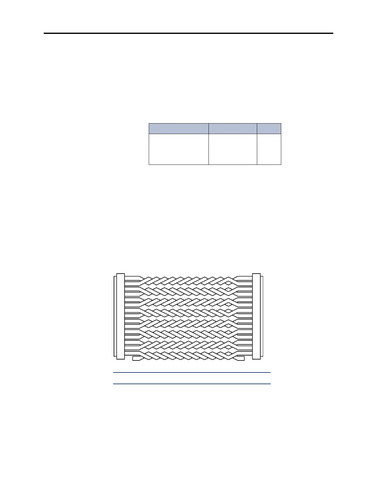
7.25 To connect the DB15 connector on the T1, E1/PRI, or T1/E1/PRI card to a DB15 con-
nector coming from the T1/PRI or PRI trunk, a flat, 28AWG (26 gauge thickness or larger --
smaller number gauge = larger thickness), twisted-pair ribbon cable with a maximum capaci-
tance of 16pF/ft may be used for distances of up to 50 feet (15 meters), as shown in the figure
below. For distances longer than 50 feet (15 meters), use the special high-speed data cable
described on page 2-54.
Figure 3-18. Using the T1, E1/PRI, or T1/E1/PRI Card's DB15 Connector
Table 3-3. T1C and T1/E1/PRI Card DB15 Connector Pin Assign-
ment
Signal Name Function Pin
Tip (Out)
Ring (Out)
Tip 1 (In)
Ring 1 (In)
Transmit Data
Transmit Data
Receive Data
Receive Data
1
9
3
11
MALE DB15 CONNECTOR
TO T1/PRI or PRI TRUNK
MALE DB15 CONNECTOR
TO T1 or E1/PRI CARD
1
9
2
10
3
11
4
12
5
13
6
14
7
15
8
1
9
2
10
3
11
4
12
5
13
6
14
7
15
8
Tip (Out)
Ring (Out)
Tip 1 (In)
Ring 1 (In)
Tip (Out)
Ring (Out)
Tip 1 (In)
Ring 1 (In)
NOTE: OUT = transmit to network, IN = receive from network