Page 3-23
Installation
INTER-TEL
®
AXXESS
®
MANUAL VERSION 11.0 – May 2008
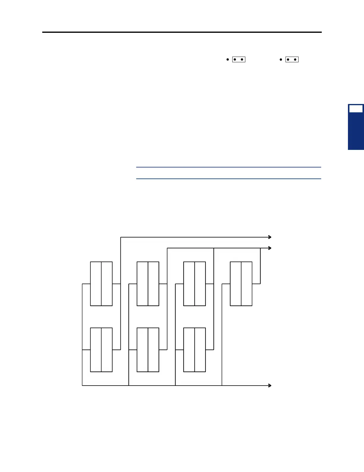
Sample MDF Block Layout and Cable Assignments (U.S. Only)
INSTALLATION
3
2.) If necessary, adjust the hybrid
balance setting from short (<.6
miles/1km) to long (>.6 miles/
1km).
3.) Replace the cover.
b. Wall-mounting the unit: The SLA can be placed horizontally on a table, or it can
be wall-mounted using the two L-shaped brackets that accompany the unit, as fol-
lows:
1.) Remove the two screws on one side of the unit and use them to attach the
two L-shaped wall mounting brackets (see Figure 3-7).
2.) Position the SLA on the MDF backboard and mark the location of the
mounting screw holes on the wall. Set the SLA aside.
3.) Drive a screw into the center of each mounting hole marking, allowing the
heads of the screws to protrude slightly.
NOTE: Use screws of sufficient strength to support the SLA.
4.)
Hang the SLA on its screws. If necessary, adjust the screws to ensure the
SLA is held firmly in place.
Figure 3-6. Sample MDF Block Layout and Cable Assignments (U.S. Only)
LG
SHT
LG
SHT
PORT 1 (J2)
PORT 2 (J5)
TO CENTRAL
OFFICE
TO STATIONS
CO TRUNKS
1-8
DKSC DKSC
SLC
LSC
CO TRUNKS
9-16
DKSC AKSC
TO SYSTEM
TO TELCOM
TO SYSTEM
1.1.1 3.1.1
3.8.1
5.1.1
5.8.11.8.1
2.1.1
2.8.1
4.1.1
4.8.1
CABLES
TO CHASSIS
CABLES STN