Page 2-9
Specifications
INTER-TEL
®
AXXESS
®
MANUAL VERSION 11.0 – May 2008
ATM Switch
SPECIFICATIONS
2
3. ATM SWITCH
3.1 Previously, the Ericsson
®
(Marconi) ForeRunnerLE
®
155 ATM Switch was used for
expanding the Axxess system to eight chassis. This switch, however, was recently replaced
with the Ericsson (Marconi) ASX™ 200BX switch. Each of these switches is described in the
following sections.
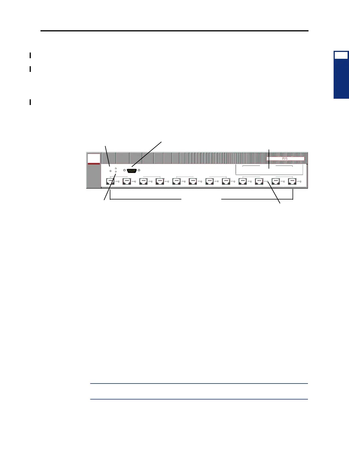
A. FORERUNNER LE 155
3.2 The Ericsson (Marconi) ForeRunnerLE 155 ATM Switch features a 2.5 Gbps, non-
blocking switching connection and an integrated CPU to reduce cost and increase reliability. It
also provides 12 ports, each with a 155 Mbps UTP Category 5 cable or MMF connector. If
necessary, one of two additional modules can be added to the expansion slot. Each module is
available with four MMF ports or two MMF and two SMF ports.
3.3 There are four ATM Switch configurations available, based on the connector type(s).
These are as follows:
• 12 UTP5 ports with two MMF and two SMF ports in the expansion slot (16 ports total);
part no. 550.5270 [IT159 in Europe]
• 12 UTP5 ports with four MMF ports in the expansion slot (16 ports total); part no.
550.5253 [IT130 in Europe]
• 12 UTP5 ports; part no. 550.5251 [IT128 in Europe]
• 12 MMF ports; part no. 550.5252 [IT132 in Europe]
3.4 Each configuration further divides the ports into interfaces. These interfaces, which are
labeled A-C (or D for a populated expansion slot), consist of four ports (1-4). Each individual
port is then identified by the interface letter and port number. For example, the third port under
Interface B is considered Port B3.
3.5 The architecture of the ATM Switch allows each interface to function independently.
Using the Element Manager, you can reset one group of ports without affecting the others. For
this reason, use a separate interface for each chassis connection when possible. For example, if
you have four chassis, connect the first to Port A1; the second to Port B1; the third to Port C1;
and the fourth to Port A2 (or D1 if populated). When configured this way, you can reset ATM
connections almost entirely on a per-chassis basis. For example, if chassis two has a bad con-
nection but chassis three is running, you can reset Interface B without bringing down the third
chassis.
NOTE: The chassis PCMAs must have the same connector types (UTP5, MMF, or SMF) as
those provided on the ATM Switch.
RST
S1
S2
Serial
Interface A
A1 A2 A3
A4
Interface B
B2B1 B3 B4
Interface C
C1 C2 C3 C4
12 PORTS
(UTP5 or MMF)
DB9 CONNECTOR
LEDs
RESET BUTTON
SLOT
EXPANSION
PORT LED