Page 2-27
Specifications
INTER-TEL
®
AXXESS
®
MANUAL VERSION 11.0 – May 2008
CPU Design Features
SPECIFICATIONS
2
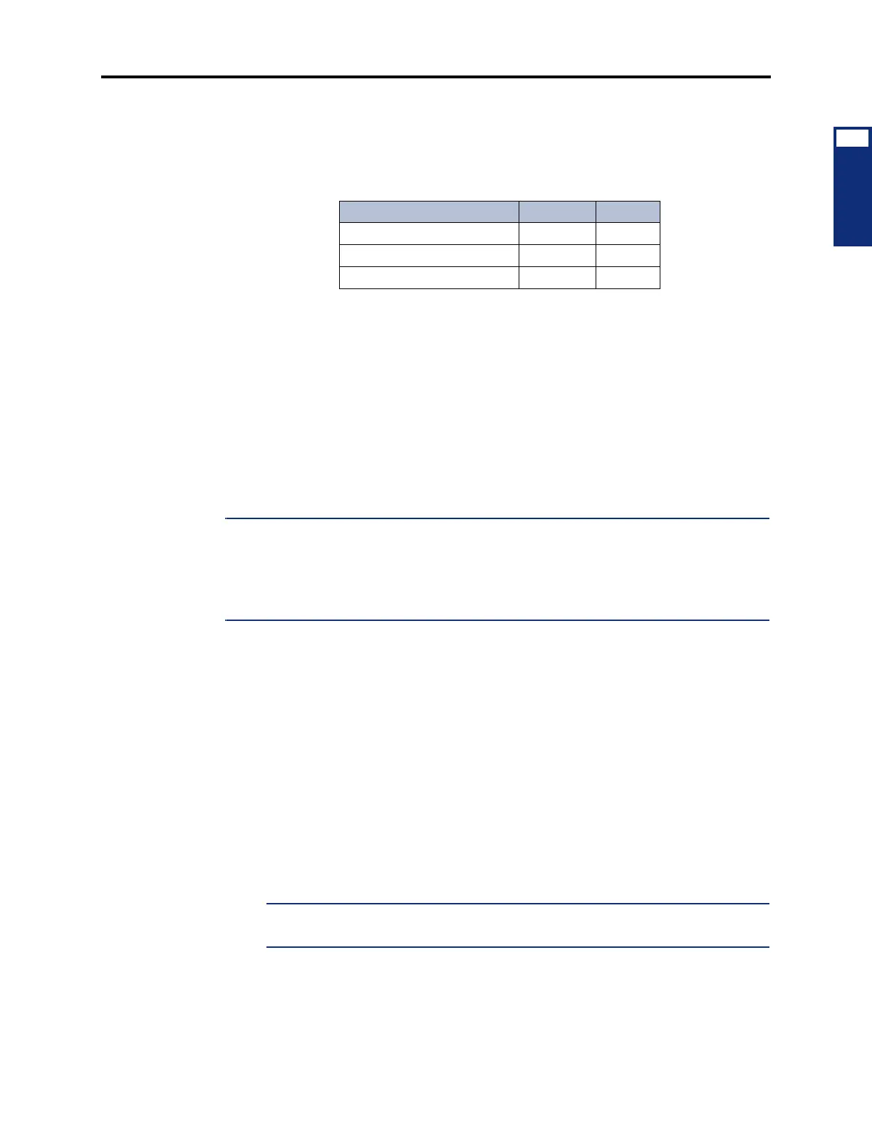
4.66 For a non-ATM system, the CPU020-D/PCM-D card can be used only in single-chassis
or dual-chassis systems. In tri-chassis or quad-chassis systems, the CPU020-Q/PCM-F card
must be used in the first (master) chassis and the CPU020-X/PCM-F card must be used in the
third (slave) chassis, as shown in the following chart (see also Figure 2-1 on page 2-11):
4.67 CPU020/PCM card combination kits are available. Each kit includes a CPU020 card, a
PCM card, the proper boot ROM and memory map PAL, and any additional memory compo-
nents required. The combined cards are shipped pre-assembled, with the current production
version system software already loaded.
4.68 Inter-Tel recommends using the CPU020/PCM card under any of the following condi-
tions:
• Systems using more than 128 ports
• Systems with unusually high call volume or extensive use of multiple ring-ins and/or
all-rings (e.g., more than 100 ringing stations per minute)
• Systems with more than one T1 or E1/PRI Card
NOTE: Inter-Tel recommends that fully-loaded phone systems, with a large number of trunks
and heavy call traffic, have extended memory added on the CPU020/PCM. Without added
memory on the CPU020/PCM, fully-loaded systems may periodically reset due to memory
shortages. The reset is the result of the CPU020/PCM attempting to recover memory. All new
CPUs purchased with versions 5.2 and later software come equipped with the extended mem-
ory installed.
4.69 For an ATM-based system, the CPU020-A/PCMA card must contain the appropriate
connector type. For example, if using multi-mode fiber (MMF), you must use the CPU020-A/
PCMA-F card. You may require more than one type of PCMA card, depending on the ATM
Switch configuration (see page 2-9). As with the CPU020/PCMs, card combination kits are
available. Each kit includes a CPU020-A card, a PCMA card, the proper boot ROM and mem-
ory map PAL, and any additional memory components required.
CPU Design Features
4.70 The CPU cards contain the following system resources (see Figures 3-48 to 3-54 on
pages 3-98 to 3-109):
• DB15 PCM Connector: (15-pin D-subminiature female connector) Connects the first
eight ports to the Audio Interface Card (AIC) in the Voice Processing PC, or connects to
the DB15 PCM connector on the Embedded Voice Mail Card (EVMC).
NOTE: In tri-/quad-chassis installations, the DB15 PCM connector on the slave PCM-
F card cannot be used to provide additional AIC ports. Use an Options Card instead.
Table 2-6. CPU020-D/PCM-D Configuration
System Configuration CPU020- PCM-
Single-/Dual-Chassis D (or Q) D (or F)
Tri-/Quad-Chassis – Master Q F
Tri-/Quad-Chassis – Slave X F