Page B-5
Appendix B — RS232
INTER-TEL
®
AXXESS
®
MANUAL VERSION 11.0 – May 2008
System Serial Port Pin Out
APPENDICES
3. SYSTEM SERIAL PORT PIN OUT
A. MODULAR JACK PIN OUT
3.1 Inter-Tel system RS232 serial ports (except for PCDPM) use a custom pin out as shown
in the diagram below. See this diagram for all RS232 connections to the serial port.
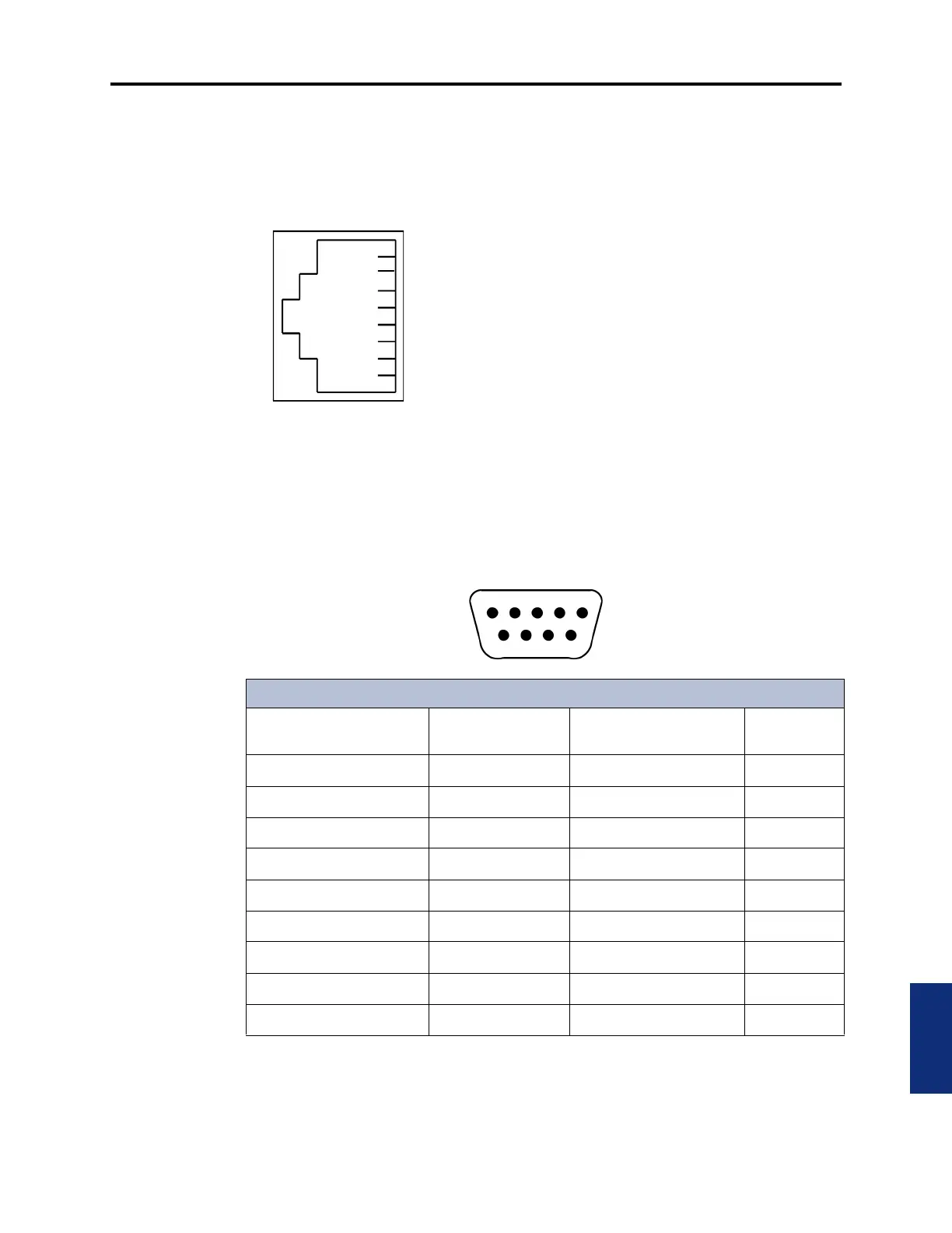
B. DB9F PIN OUT
3.2 Inter-Tel PCDPMs use the de facto industry standard DB9F pinout configured as a DCE
device. See the following diagram for all PCDPM connections.
1
2
3
4
5
6
7
8
*The serial port on the CPU-112 card (not supported by system version 5.0 or later),
does not have the Input Flow Control pin connected, but it can use the Output Flow Con-
trol pin. The two serial ports on a MEM card have both flow control pins connected;
therefore, they can perform hardware flow control as the other Inter-Tel ports do.
SIGNAL TYPE
No Connect
No Connect
Ground
Data
Flow Control
Data
Port Ready
Flow Control
SIGNAL DIRECTION
Input To System
Input To System*
Output From System
Output From System (always asserted)
Output From System
PCDPM DB9F Connector
Description
RS232 Equivalent
Pin Name
Direction (DCE) DB9F Pin No.
Always True DCD Output from System 1
Output Data RD Output from System 2
Input Data TD Input to System 3
Input Flow Control (DTR) DTR Input to System 4
Ground GND 5
Always True DSR Output from System 6
Input Flow Control (RTS) RTS Input to System 7
Output Flow Control CTS Output from System 8
Not Supported RI No Connection 9