Page 3-133
Installation
INTER-TEL
®
AXXESS
®
MANUAL VERSION 11.0 – May 2008
Equip the BRI Ports
INSTALLATION
3
Equip the BRI Ports
10.53 After the card is equipped, the installer can equip the eight individual ports by choosing
the Ports sub-folder under each card’s folder, located under System\Cabinets. The default
device type is None. Both BRS and BRU ports can be equipped as station or trunk ports. The
choices for the ports on the drop-down list are Station/Station, Trunk/Trunk, and None. Ports
may be unequipped by setting the port type to None. See below for more details.
10.54 When a trunk port is equipped, the installer must choose an extension for each newly
equipped B-channel trunk. The default extension number of a B-channel trunk on a BRI trunk
port is 94XXX, where XXX is determined by the formula [(B-1)*32 + (P-1)*2 + D], where B
indicates board number, P indicates port number, and D denotes device number. The hardware
address of each trunk has the form NN:BB:PP:CC, where NN is the node number, BB is the
board number, PP is the port number, and CC is the circuit number.
10.55 An extension must also be chosen for each equipped station port. The default extension
number of a B-channel station on a BRI station port is 1XXX, following the same rules as nor-
mal station extension numbers. The hardware address of each station is NN:BB:PP:CC, just as
for trunk circuits. The BRS and BRU ports can be equipped as follows:
BRS Ports Programmed as Trunk Ports
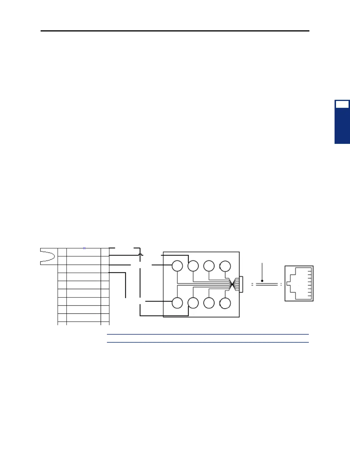
10.56 The following is an example of the termination between a BRS (T) trunk port and an
NT1 device using four-wire connection. The BRS ports are programmed or equipped as trunk
ports that connect to an NT1.
Figure 3-65. BRS Trunk/Trunk Port to NT1
NOTE: See page 3-38 for more information on the BRS card connection.
MDF to 8-Pin RJ45 Modular Jack for the BRS Ports
TXP0(R)
RXP0(R1)
RXN0(T1)
TXN0(T)
MODULAR JACK ASSEMBLY
66M50
TIP
(OUT)
TIP1
(IN)
RING
(OUT)
RING1
(IN)
5
6
7
8
4
3
2
1
1
3
5
7
2
4
6
8
1
2
3
4
5
6
7
8
T
T1
R1
R
4-Pair,
Non-reversing
MOD-to-MOD
Line Cord
G
Y
BR
S
R
BK
O
BL
RJ45



 To Next Page