Page 5-56
System Features
INTER-TEL
®
AXXESS
®
MANUAL VERSION 11.0 – May 2008
Standard T1 Trunks
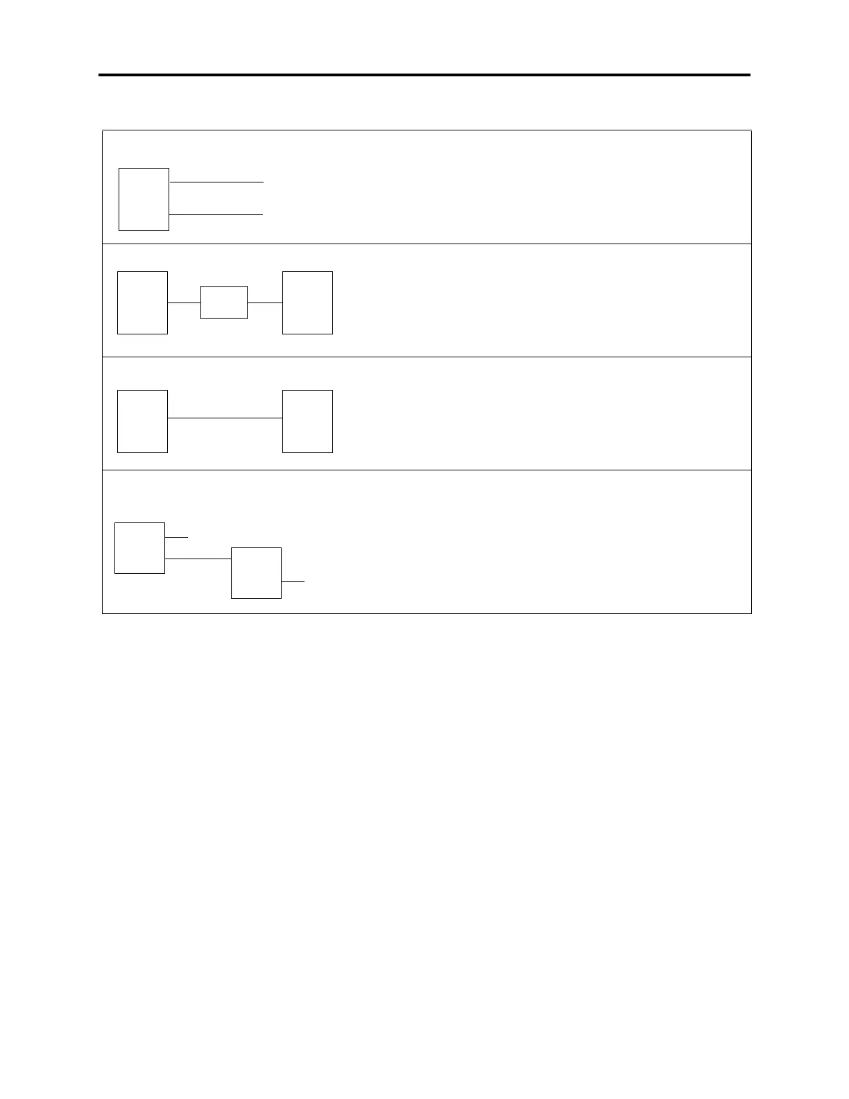
Table 5-10. T1 Trunk Applications
In this application, the T1 cards are connected directly to the central
office. The line buildout is programmed to support the distance to the
CO (or nearest repeater). Both cards draw reference clock from the
public network and are slave clocks. One card is designated as the
system reference clock.
In this application, two Inter-Tel systems are connected through a T1
repeater. Both T1 cards have the line buildout programmed to support
the distance to the T1 repeater. One card is designated as the master
clock and the other is the slave clock (that receives reference from
the master clock).
In this application, two Inter-Tel systems are connected directly to
each other. The T1 cards have the line buildout programmed to sup-
port the distance between the Inter-Tel systems. One card is desig-
nated as the master clock and the other is the slave clock (that
receives reference from the master clock).
In a T1 network that involves multiple CO and T1 card connections,
the line buildout is determined by each connection. In the example
shown here, the two T1 cards connected to the CO receive reference
clock from the public network and are slave clocks. The two that are
connecting the Inter-Tel systems do not draw reference from the pub-
lic network. T1 #2 on System #1 is the master clock and T1 #1 on
System #2 is a slave clock.
System-to-CO
T1 #1
CO
6000’ max.
6000’ max.
T1 #2
CO
System-to-System with repeater(s)
Master
System
T1C
6000’
max.
Slave
System
T1C
6000’
max.
T1
repeater
System-to-System without repeaters
Master
System
T1C
Slave
System
T1C
6000’ max.
Sample T1 Network
T1 #1
CO 1
T1 #1
CO 2
System #2
System #1
T1 #2
T1 #2