Installation
INTER-TEL
®
AXXESS
®
MANUAL VERSION 11.0 – May 2008
Page
3-24
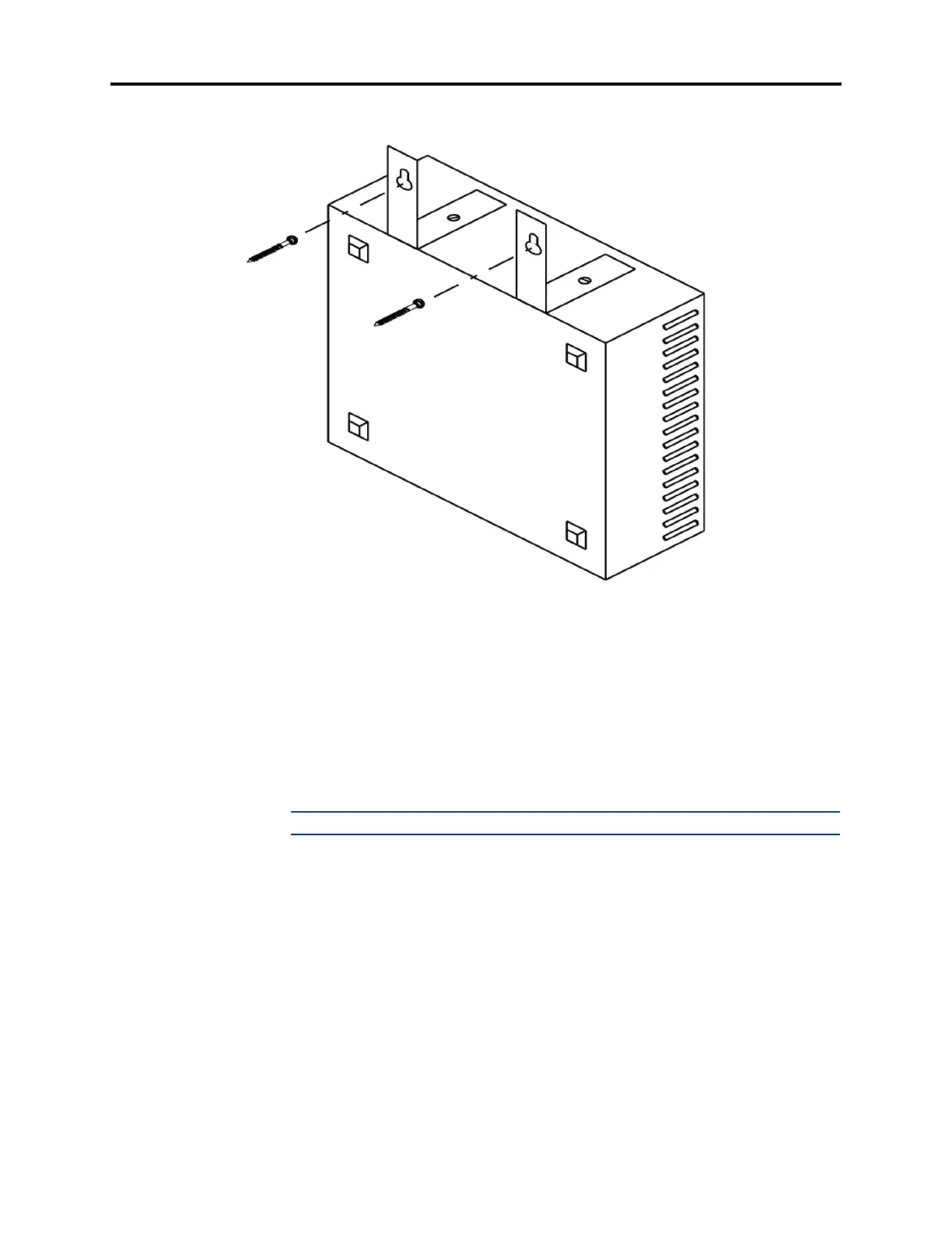
Wall Mounting the SLA
Figure 3-7. Wall Mounting the SLA
A. CONNECTING THE TRUNK CABLES TO THE MDF
CO Trunks in a U.S. system
7.4 Connect the CO trunks and Loop/Ground Start Card (LGC) and/or Loop Start Card
(LSC) cables as outlined below. Note that step 2 mentions two installation methods. Although
the first method is more flexible, the second method can be used to minimize the number of
terminal blocks that are used. Refer also to Figures 3-9 and 3-10 on pages 3-27 and 3-28.
1. Cross connect the CO trunks from the telephone company RJ-type blocks to the right
side of the LGC/LSC blocks.
NOTE: For additional lightning protection, see paragraph 7.9.
2.
Method A: Using enough 25-pair cable to run from the LGC/LSC blocks to the cards,
make the termination cables. Attach a 50-pin female amphenol-type connector to one
end of each LGC/LSC cable. Label each connector and cable end with the appropriate
slot number (e.g., SLOT-6). These connectors are attached to the cards after they are
installed in the equipment chassis.
Method B: Using enough 25-pair cable to run from the LGC/LSC blocks to the cards,
make the special termination cables. Attach up to three, 50-pin female amphenol-type
connectors to one end of each LGC/LSC cable as shown in Figure 3-10. Connect CO
trunks 1-4 (or 1-8 if a LGC or LSC Daughter Card is installed) to one connector, trunks
5-8 (or 9-16) to another connector, trunks 9-12 (or 17-24) to a third connector, and so
on for each cable. Label each connector with the appropriate slot number (e.g., SLOT-
6). These connectors are attached to the cards after they are installed in the equipment
chassis.