Page 3-201
Installation
INTER-TEL
®
AXXESS
®
MANUAL VERSION 11.0 – May 2008
Optional Modem Data Port Modules (MDPMs)
INSTALLATION
3
Optional Modem Data Port Modules (MDPMs)
13.26 Digital phones equipped with PC Data Port Modules may be equipped with optional
Modem Data Port Modules – part no. 550.3015 [PB2549-A in Europe]. The MDPM contains a
four-conductor modular jack (line jack unit) that can be used to connect a data device (such as
a personal computer with a direct-connect modem) or a single-line set to the phone.
NOTE: Each “equipped” MDPM installed counts as one single-line device.
13.27 The data device can be used by the associated phone(s) to communicate with remote
data equipment over voice channels being used for CO or intercom calls. The data device’s
modem must be externally powered (or capable of operating on 20mA of loop current) and
have an RJ11 CO trunk interface.
13.28 The data device can be activated by the associated phone(s) or by an auto-dial modem.
(For more details, see page 5-269 in FEATURES). The data device is disconnected whenever
one of the following occurs: the modem attached to the phone disconnects from the call, the
called modem disconnects from the call, or the data connection is transferred to the phone’s
primary voice path and the call is disconnected.
13.29 Install the MDPM and attach the data device as outlined below. For diagrams of the
installation, see Figure 3-87 on page 3-200 and see Figure 3-91 below.
1. Ensure the phone line cord is unplugged from its modular jack (line jack unit) on the
phone.
2. Plug the free end of the PCDPM-to-MDPM interface cable into connector J1 on the
MDPM. (The other end of the cable was previously attached to the PCDPM; see
page 3-191.)
3. Insert the modem line cord (which would normally be connected to a CO jack) into the
modular jack (J2) on the MDPM.
4. Plug the main AC transformer unit into an available AC power source. DO NOT use the
outlet for the equipment chassis.
5. Reconnect the phone line cord. The MDPM can be placed flat or standing on end.
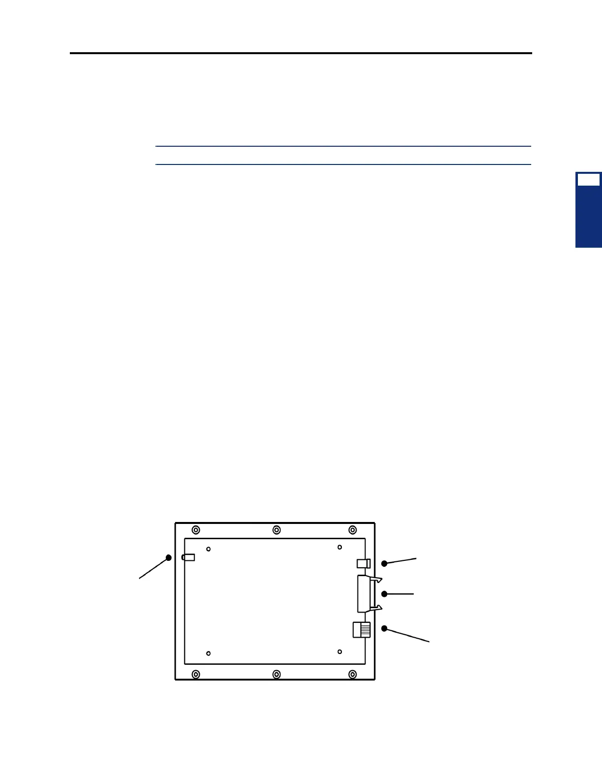
Figure 3-91. Digital Phone Modem Data Port Module (MDPM) Installation
MODEM DATA PORT MODULE
LED
INDICATORS
(stacked)
POWER CONNECTOR
PCDPM CONNECTOR
MODULAR JACK
(TOP COVER REMOVED)
TO AC TRANSFORMER
TO PC DATA PORT MODULE
TO DATA DEVICE
OR SL SET
POWER
OFF HOOK
RINGING