Page 2-28
Specifications
INTER-TEL
®
AXXESS
®
MANUAL VERSION 11.0 – May 2008
CPU Design Features
• RS232 Jacks: (three 8-pin, 8-conductor modular jacks/line jack units on the CPU020-
D/-Q, one on the CPU020-X) Connects to the RS232 port on the Voice Processing PC
or EVMC, or connects SMDR/error message output devices, a personal computer for
programming the system database, and/or a modem for remote programming/mainte-
nance (see pages 2-99 to 2-104 for requirements).
NOTE: The system can have a maximum of 32 RS232 ports for system services. This
includes the RS232 ports on the CPU card, Options Card(s), and PC Data Port Mod-
ules. If an Inter-Tel Voice Processing PC or EVMC is installed, at least one of the sys-
tem RS232 ports must be dedicated to Voice Processing.
• RJ45 Jack (on PCMA-C only): Connects the CAT5 cable to the appropriate connec-
tors on the ATM Switch. The maximum length for this connection is 100 meters (.06
miles).
• LED Indicators: Shows main processor operation (CPU ACTIVE - green), database in
default state due to error (DATABASE ERROR - red), minor system alarms (MINOR
ALARM - yellow), external clock activity (EXTERNAL CLOCK ACTIVE - green),
and database back-up battery connection (BATTERY OFF - red). The PCM-F card has
two additional LEDs that show local fiber-optic status (LOCAL SYNC - green) and
remote fiber-optic status (REMOTE SYNC - green). The PCMA cards include an ATM
LED that indicates when there is no active connection to the ATM Switch (ATM LINK
BAD - red). See Figure 7-2 for detailed LED information.
• Fiber-Optic Jacks (on PCM-F, PCMA-F, and PCMA-FS only): Installed as one
transmit and one receive on each PCM-F card for connecting the CPU020-Q/PCM-F
card in the first (master) chassis to the CPU020-X/PCM-F card in the third (slave) chas-
sis. The fiber-optic jacks on the PCMA-F and PCMA-FS cards are used to connect to
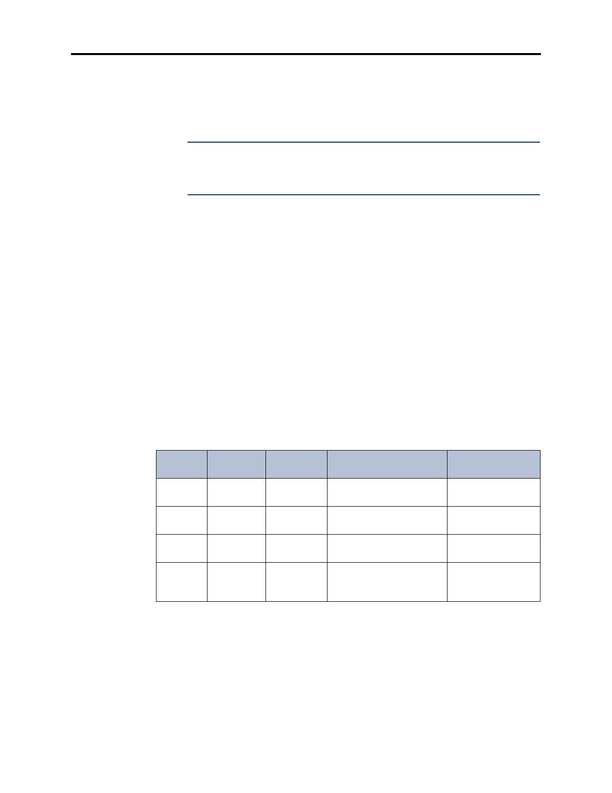
the OC-3 connectors on the ATM Switch. See the table below for loop limits without
repeaters.
Table 2-7. Fiber-Optic Jack Loop Limits
Desc. Connector
Connects
To
Medium Maximum Length
512CPU ST Slave Multimode Fiber (62.5/125
outer/inner core in microns)
1 km (.6 miles)
512CPU/
EAC
ST CPS Multimode Fiber (62.5/125
outer/inner core in microns)
1 km (.6 miles)
PCMA-F SC ATM Switch Multimode Fiber (62.5/125
outer/inner core in microns)
2 km (1.2 miles)
PCMA-FS SC ATM Switch 1320 nm Single Mode Fiber > 2 km (1.2 miles)
but less than 15 km
(9.3 miles)