Page 2-29
Specifications
INTER-TEL
®
AXXESS
®
MANUAL VERSION 11.0 – May 2008
CPU Design Features
SPECIFICATIONS
2
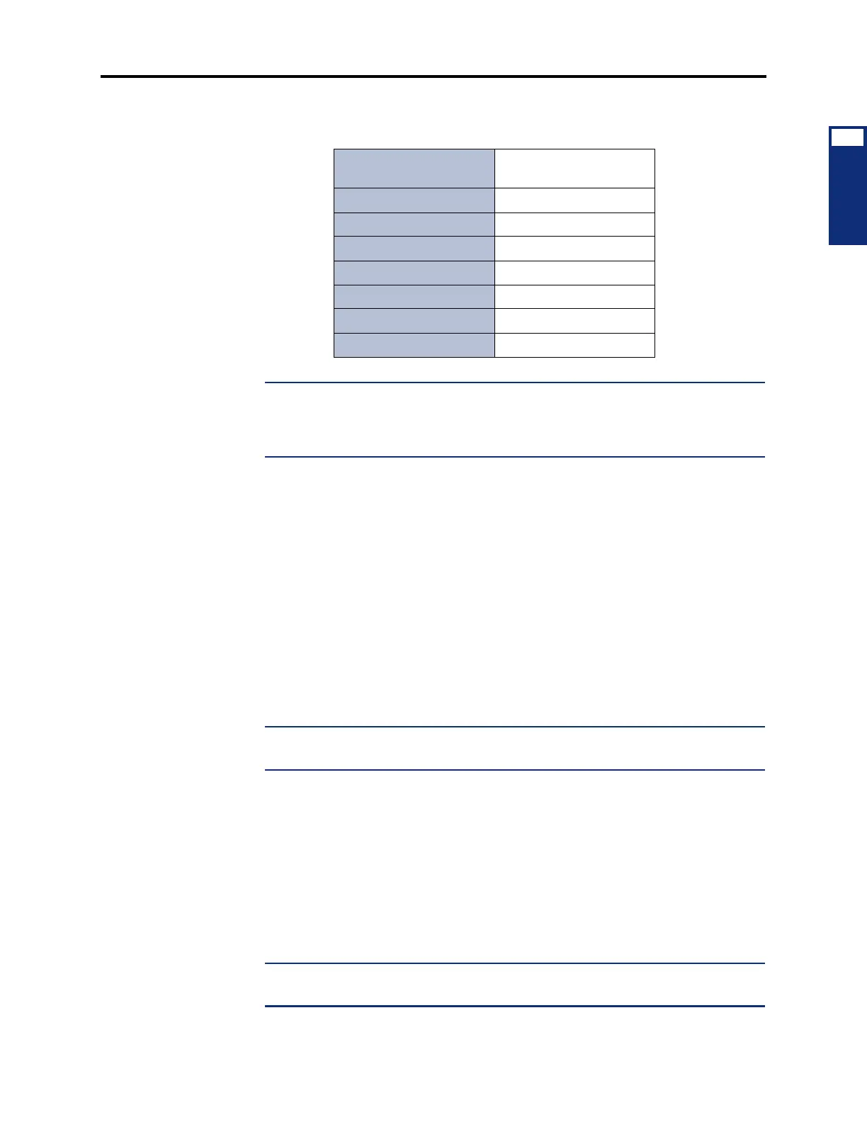
For more information about the 512 CPUs, see the following chart.
NOTE: A ten-foot (3-meter) cable is available using part no. 813.1628 [C118 in
Europe]. Or, if necessary, contact Inter-Tel's CommSource™ division or Inter-Tel Europe
for information on purchasing longer cable lengths. Custom cables can also be built
using industry-standard ST-type connectors.
• Reset Switch: (one in single-/dual-chassis systems, two in tri-/quad-chassis systems,
four in ATM systems with eight chassis) Manually resets the system during trouble-
shooting. This is a software-controlled system reconfiguration. Pushing this switch does
the following:
— Preserves the battery-backed database information, all calls in progress, outside
calls being dialed, pages in progress, camped-on calls, queue requests, system and
user programming, inter-station messages, calls on system and individual hold,
do-not-disturb messages, and reminder messages.
— Restores DTMF receivers, modem access, and speech channels, and resets the sta-
tion clocks to match the system clock. Updates trunk button, DSS/BLF button,
speed-dial button, and feature button lamp status.
— Disconnects calls ringing in and all ISDN calls in progress.
NOTE: If necessary, the reset switch can also be used to place the CPU card into
“receive software upload” mode, as described on page 3-170.
• Database Back-Up Battery: (3.6V, ½AA lithium battery) Supports the database for at
least two months of accumulated system down time.
• Battery Voltage Test Points And Check Button: Checks the database back-up battery
charge. If the battery voltage is not greater than 3.3VDC, replace the battery.
• Battery Back-up Jumper Strap: Activates the database back-up battery. The jumper
strap should be placed in the ON position (over the bottom two pins) before the CPU
card is installed. When the card is taken out of service for repair or storage, the jumper
strap should be placed in the OFF position (top two pins) to preserve the battery charge.
NOTE: Placing the BATTERY jumper strap in the OFF position erases the database
when the card is unplugged or loses power.
Table 2-8. 512 CPU
Fiber Diameter 62.5/125 (outer/inner core
in microns)
Mode Multi-Mode
Wavelength 820 nm
Maximum Attenuation 5 db/km
Terminating Connector ST
Pairs 1
Maximum Length 1 km (.6 miles)
B-L Product 20 MHz-km