Installation
INTER-TEL
®
AXXESS
®
MANUAL VERSION 11.0 – May 2008
Page
3-104
Installing CPU020/PCM or CPU020/PCMA Cards
CPU020-A/PCMA-F/PCMA-FS/PCMA-C: See Figures 3-53 and 3-54 on pages 3-110
and 3-111 for LED indicator locations.
* When a new system is installed, the DATABASE ERROR LED remains lit until the system data-
base has been programmed. The MINOR ALARM LED may also be lit and can later be cleared
from an administrator station using the Clear System Alarm feature code (default is 9850).
7. While power is ON, press the battery check button on the CPU020-D/PCM-D or
CPU020-A/PCMA card to measure the database back-up battery voltage. The voltage
test points (TP1 to TP2) are located on the front edge of the card. Insert the “common”
voltmeter probe into the ground point (TP2) and insert the other probe into the voltage
test point (TP1). If the voltage is not greater than 3.3VDC, replace the battery as
described on page 3-112. (See Figure 3-50 on page 3-107 for back-up battery voltage
test point locations.)
8. If the CPU020/PCM or CPU020/PCMA card does not have the appropriate system soft-
ware already installed in flash memory, see page 3-173 to upload the software from the
programming PC to the card.
9. After installing the CPU020/PCM or CPU020/PCMA card, the optional music source,
external paging equipment, Voice Processing PC, power failure transfer equipment, out-
put device, etc. may be connected to the CPU020/PCM or CPU020/PCMA card at any
time. (See page 3-213 for Voice Processing PC installation instructions, to page 3-240
for external music source installation instructions, and to page 3-242 for external paging
equipment installation instructions.)
NOTE: The fiber-optic cable is attached to the FIBER TRANSMIT and FIBER
RECEIVE jacks after the PCM-F card in the third (slave) chassis is installed. See
page 3-104 for details.
10.
Turn OFF the AC POWER switch.
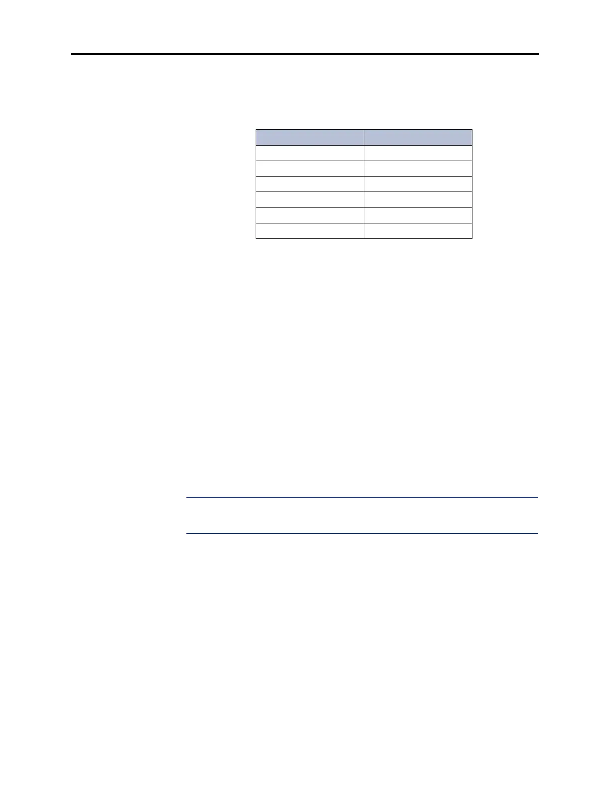
Table 3-16. CPU020-A/PCMA-F/PCMA-FS/PCMA-C LED
Indications
Name Correct Indication
Battery Off Off (Red)
CPU Active Lit (Green)
Database Error Off* (Red)
Minor Alarm Off* (Yellow)
External Clock Active Off (Green)
ATM Link Bad Off (Red)