Page B-9
Appendix B — RS232
INTER-TEL
®
AXXESS
®
MANUAL VERSION 11.0 – May 2008
Flow Control
APPENDICES
8. FLOW CONTROL
8.1 Flow control tells each device (such as the system serial ports and the PC serial port)
when it can transmit data and when it must stop transmitting data.
8.2 There are two types of hardware flow control commonly found in the industry:
• DTR/CTS hardware handshake (commonly used by printers and other devices, but not
supported by any formal standard)
• RTS/CTS hardware handshake (now supported by the EIA/TIA-232-E standard)
8.3 When the system is in the default configuration, the Inter-Tel system RS232 ports are
enabled for software flow control. Most output devices are designed for software flow control,
which is the use of “X-ON” and “X-OFF” characters to indicate readiness to send or receive
data. Refer to the device’s operating manual to determine if it uses X-ON/X-OFF characters.
8.4 The PCDPM RS232 connection supports only hardware flow control and hardware
flow control is always enabled. The reason that the PCDPM supports only hardware flow con-
trol, and that hardware flow control is enabled at all times, is because the data input buffer in
the phone is very small; it is only 15 bytes. This means that the other device (typically a PC)
connected to the PCDPM must also enable hardware flow control and observe the output flow
control signal (CTS) from the PCDPM for the connection to work properly.
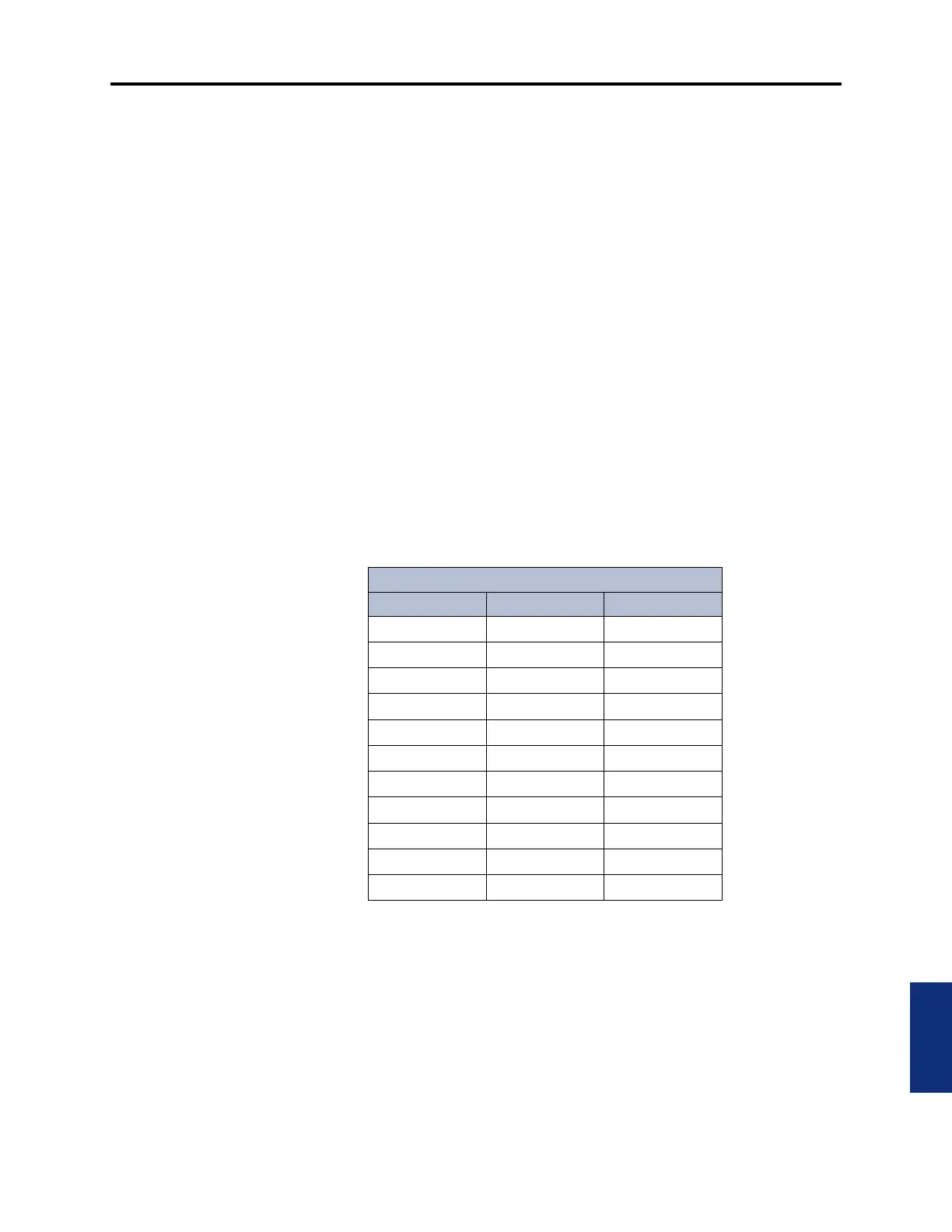
8.5 The flow control truth table for the most recent model PCDPM (marked with artwork
number 826.5239-5 or later) is shown below:
8.6 Note that RTS takes on the functionality of “Ready for Receiving.”
• Off = Negative voltage (less than -3V).
• On = Positive voltage (greater than +3V).
• No Connect = The pin is not connected to the anything and is therefore considered
“floating” or “open.”
• Go = The PCDPM transmits data to the PC.
• Stop = The PCDPM does not transmit data to the PC.
Table B-1. PCDPM Flow Control Truth Table
PCDPM Flow Control Truth Table
DTR RTS Result
No Connect No Connect Stop
No Connect Off Stop
No Connect On Go
Off No Connect Stop
Off Off Stop
Off On Stop
On No Connect Go
On Off Stop
On On Go