Installation
INTER-TEL
®
AXXESS
®
MANUAL VERSION 11.0 – May 2008
Page
3-38
Connect Devices to the BRS Cards
• External power supply: This power supply is provided with the device and plugs into
a wall socket.
7.31 The BRS transmit pairs connect to the receive pairs of the terminating device, without
regard for signal polarity. (The installer must determine which pairs are transmit and receive
for the terminating device.)
7.32 Install the BRS cards in the selected slot in the equipment chassis, and connect the
external power supply, if required. Also connect the 50-pin Amp connection to the front of the
card and terminate the cable to the MDF (Main Distribution Frame).
7.33 Install the BRU card in the selected slot in the equipment chassis, and connect the 50-
pin Amp connection to the front of the card, and then terminate the cable to the MDF.
NOTE: The jumper should have an orientation that connects the pins horizontally. For example,
in the default position, the jumper connects pins 5 to 6 and 7 to 8. See Figure 3-63 on page 3-
133 for jumper positioning.
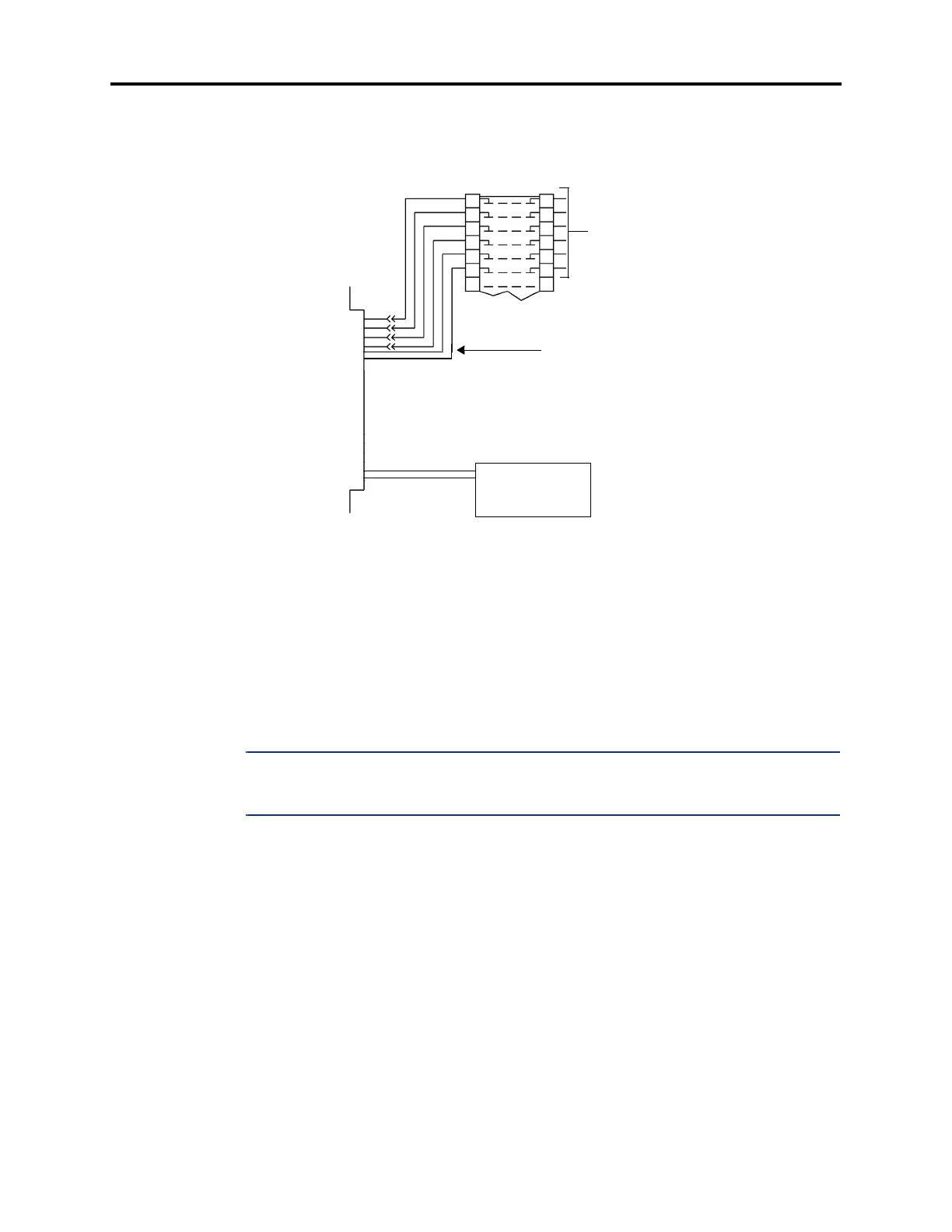
TX
TX
RX
RX
-48V
TO THE DEVICE
-48V FO
BRS
CARD
RET
-48V RET
-48V RET
-48V
This -48 volts is distributed on
the third pair to each BRS Device
from the MDF.
EXTERNAL 48VDC
POWER SUPPLY
CONNECTOR (J7)
(P/N 813.1740)