2-112 MACHINE OPERATIONS OPERACIONES DE MECANIZADO
<Lead Angle>
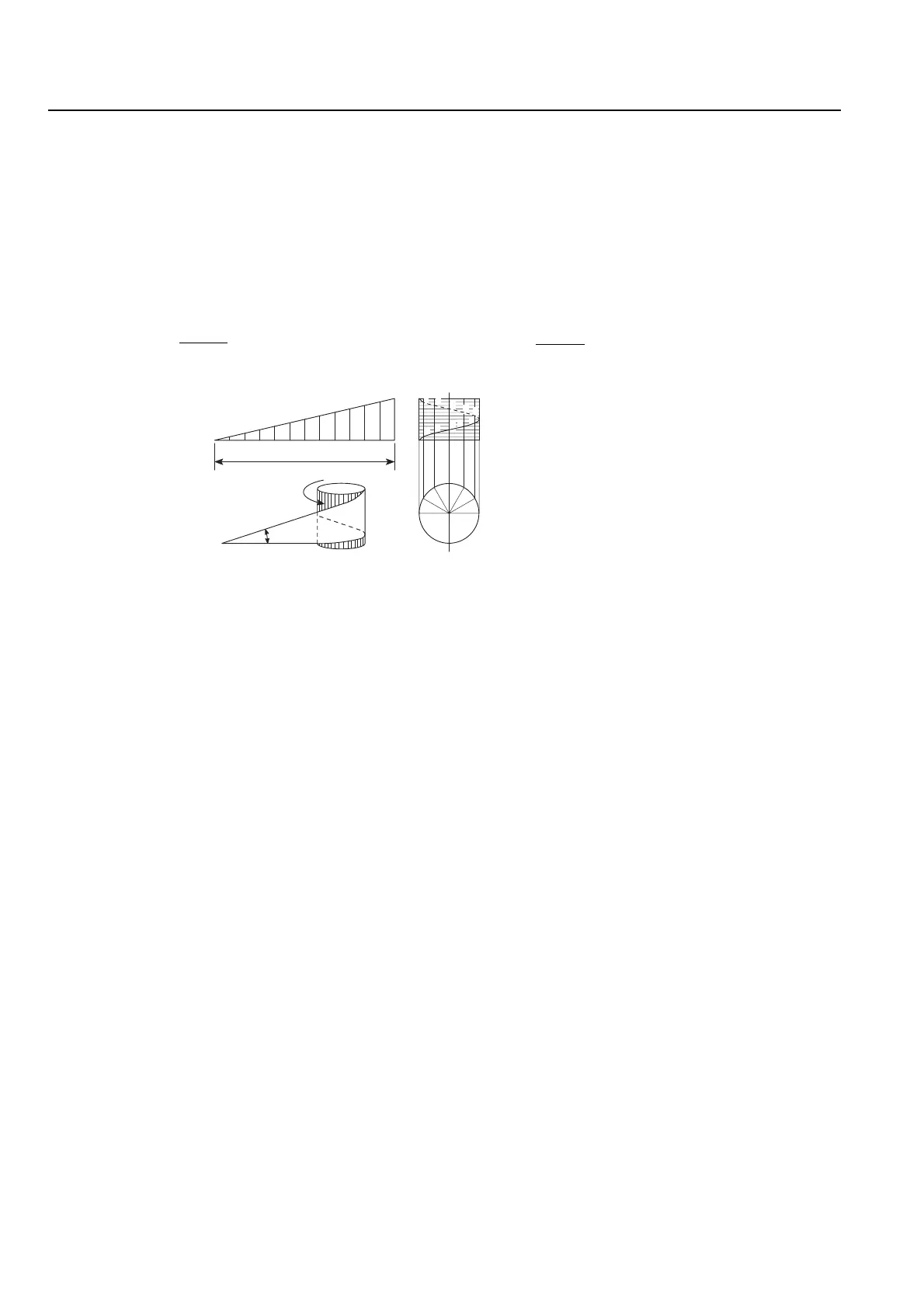
As shown in the diagram below, when triangle "abc"
is wound around a cylinder, the oblique line "ac" of
the triangle forms a helical curve. If a groove having
a triangular or square cross-section is created along
the helix, a thread is formed.
∠cab = θ of triangle "abc" forming the helix is called
the lead angle. In order to cut the thread smoothly,
movements from point 3 to point 8 must generate the
same angle as the lead angle.
The lead angle can be calculated using the following
formula.
tanθ =
<Ángulo de guía>
Como se muestra en el diagrama a continuación, cuando el
triángulo "abc" se bobina en un cilindro, la línea oblicua "ac"
del triángulo forma una curva helicoidal. Si una ranura con
sección transversal triangular o cuadrada se crea a lo largo
del hélice, se forma un filete.
∠cab = θ del triángulo "abc" formando el hélice se llama
ángulo de guía. Para un fileteado lígero, los movimientos
desde el punto 3 al punto 8 deben generar el mismo ángulo
de guía.
El ángulo de guía podrá calcularse mediante la siguiente fór-
mula.
tanθ =
1. Point 1 → Point 2
The radius of the approach arc must satisfy the
following conditions.
Tool radius < r (approach arc radius) < Machining
radius
By assigning tool radius 10 mm and machining
radius 30 mm to the inequality above, the
following can be obtained.
10 < r < 30
From this, approach radius is determined as
r = 18 mm.
<Coordinate Values of Approach Arc Radius
Start Point>
If the inside angle of the approach arc is too
large, the approach motion will take time to
complete. Conversely, if the inside angle is too
small, the tool may interfere with the face to be
machined. Taking these facts into consideration,
the inside angle of the approach arc is
determined to be 90°. According to the approach
radius and the machining radius, the coordinate
values of the approach arc center are Y0,
Z−28.0. The coordinate values of start point 2
are then calculated as Y−18.0, Z−28.0.
2. Point 2 → Point 3
<Lead in Approach Arc>
To execute thread cutting smoothly, the lead
angle within the approach arc must match the
lead angle of the thread to be cut.
Machining radius : Pitch (Lead)
= Approach arc radius : L (Lead)
Since "machining radius = 30 mm", "pitch =
2 mm", and "approach arc radius = 18 mm",
30 : 2 = 18 : L
Accordingly, value L is obtained as follows:
L = 1.2 mm
1. Punto 1 → Punto 2
El radio del arco de acercamiento debe cumplir las
condiciones siguientes.
Radio de herramienta < r (radio del arco de
acercamiento) < Radio de mecanizado
Asignando 10 mm al radio de herramienta y 30 mm al
radio de mecanizado en la desigualdad anterior, se
puede obtener el resultado siguiente.
10 < r < 30
Así se puede determinar el radio de acercamiento como
r = 18 mm.
<Valores de coordenadas del punto de inicio del radio
del arco de acercamiento>
Si el ángulo interior del arco de acercamiento es
demasiado largo, el movimiento de acercamiento
tardará en acabarse. A lo contrario, si el ángulo interior
es demasiado pequeño, la herramienta puede interferir
con la cara que se mecanizará. Teniendo esto en
cuenta, el ángulo interior del arco de acercamiento se
determina como 90°. De acuerdo con el radio de
acercamiento y el radio de mecanizado, los valores de
coordenadas del centro del arco de acercamiento son
Y0, Z−28.0. Los valores de coordenadas del punto de
inicio 2 se calculan entonces como Y−18.0, Z−28.0.
2. Punto 2 → Punto 3
<Guía en el arco de acercamiento>
Para que se ejecute el fileteado de manera regular, el
ángulo de guía del arco de acercamiento tiene que
corresponder con el ángulo de guía del filete que se va a
cortar.
Radio de mecanizado : Paso (guía)
= Radio del arco de acercamiento : L (guía)
Debido a que "radio de mecanizado = 30 mm", "paso =
2 mm" y "radio del arco de acercamiento = 18 mm",
30 : 2 = 18 : L
Por consiguiente, el valor L se obtiene de la manera
siguiente:
L = 1,2 mm
L
π • D
L
π • D
12
6
1
2
3
4
5
6
7
8
9
10
11
12
a
b
c
θ
1
2
3
4
5
0
6
7
89
10
11
12
1
2
a
b
c
3
4
5
9
7
8
10
11
0
πD
θ: Lead angle (°)
Ángulo de guía (°)
L: Lead (mm)
Guía (mm)
D: Thread diameter (mm)
Diámetro de filete (mm)
 Loading...