2-116 MACHINE OPERATIONS OPERACIONES DE MECANIZADO
Programming using G07.1 (G107) Programación mediante G07.1 (G107)
After selecting the cylindrical interpolation mode with
the G07.1 (G107) command, specify the command
points in order.
Tras haber seleccionado el modo de interpolación cilíndrica
con la instrucción G07.1 (G107), especifique los puntos de
instrucción por orden.
8. With headstock 2 specifications, the cylin-
drical interpolation function can be used
for spindle 2 in addition to spindle 1. If the
cylindrical interpolation function is used in
the spindle 2 operation, pay close atten-
tion to the "+/−" direction of the Z- and C-
axes.
Concerning the "+/−" direction of the
Z- and C-axis, "Axis Control and
Direction" (page 1-79).
NOT A
8. Con las especificaciones de cabezal fijo 2, la fun-
ción de interpolación cilíndrica podrá usarse para
el husillo 2 además del husillo 1. Si se usa la fun-
ción de interpolación cilíndrica en la operación de
husillo 2, preste atención a la dirección "+/−" de
los ejes Z y C.
Respecto al sentido "+/−" de los ejes Z y C,
"Control del eje y dirección" (página 1-79).
360°
200°
100°
R4
R4
R4
R4
30 10
C
B
A
C
8
110
φ
A
B
C
160°
100°
100°
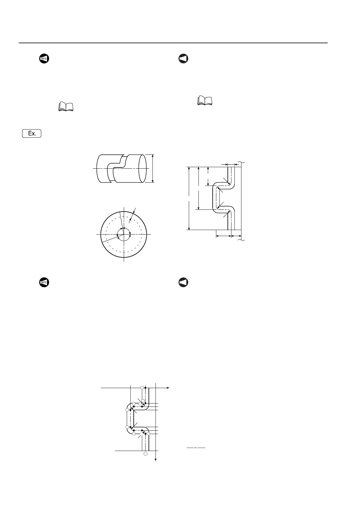
Fig. 1
Fig. 1
Fig. 3
Fig. 3
Fig. 2
Fig. 2
Groove Depth 5 mm
Profundidad de la ranura 5 mm
1. Fig. 2 is a development of Fig. 1. The
angle in Fig. 2 indicates the angle made to
the center of the cylinder as shown in
Fig. 3.
2. Command point for cylindrical interpola-
tion is obtained from the development of
the circumference of the cylindrical shape
(Fig. 2).
3. The development of the cylinder circum-
ference (Fig. 2) is given in the ZC plane.
4. Command points of the shape in Fig. 2 are
expressed by • in Fig. 4.
NOT A
1. La Fig. 2 es un desarrollo de la Fig. 1. El ángulo
de la Fig. 2 indica el ángulo formado en el centro
del cilindro tal y como se muestra en la Fig. 3.
2. El punto de instrucción para la interpolación cilín-
drica se obtiene a partir del desarrollo de la cir-
cunferencia de la forma cilíndrica (Fig. 2).
3. El desarrollo de la circunferencia del cilindro
(Fig. 2) se indica en el plano ZC.
4. Los puntos de instrucción de la forma de la Fig. 2
se expresan mediante • en la Fig. 4.
0
−10−40
C1
100 (A)
C2
C3
200 (B)
C4
360
1
10
2
3
4
5
6
7 9
R4
R4
R4
R4
8
Z-Axis (mm)
Eje Z (mm)
Each Corner: R4
Cada esquina: R4
C-Axis ( °)
Eje C ( °)
Fig. 4
Fig. 4
Path of the Tool Center
Trayectoria del centro
de la herramienta
•: Command Point
Punto de instrucción
:
 Loading...