2-118 MACHINE OPERATIONS OPERACIONES DE MECANIZADO
Next, calculate values C1 to C4 in "mm".
C1: 87.266 − 4 = 83.266 (mm)
C2: 87.266 + 4 = 91.266 (mm)
C3: 174.533 − 4 = 170.533 (mm)
C4: 174.533 + 4 = 178.533 (mm)
For cylindrical interpolation, it is necessary to specify
the C-axis value in angles.
Convert C1 to C4 into the unit of "°" (angle).
A continuación, calcule los valores C1 a C4 en "mm".
C1: 87,266 − 4 = 83,266 (mm)
C2: 87,266 + 4 = 91,266 (mm)
C3: 174,533 − 4 = 170,533 (mm)
C4: 174,533 + 4 = 178,533 (mm)
Para la interpolación cilíndrica, será necesario especificar el
valor del eje C en ángulos.
Convierta C1 a C4 en la unidad de "°" (ángulo).
O1;
N1;
M45;
G28 H0;
G00 T0101;
G97 S100 M13;
X115.0 Z−10.0 S500;. . . . . . . . . . . . . . . . . . . . . . Positioning to the point where
grooving is started
Posicionamiento en el punto
donde se inicia el ranurado
G98 G01 X100.0 F50; . . . . . . . . . . . . . . . . . . . . . Starting of the grooving
Feedrate is 50 mm/min,
specified in the G98 (feed per
minute) mode.
Inicio del ranurado
La velocidad de avance es
50 mm/min, especificada en el
modo G98 (avance por minuto).
G19 W0 H0;. . . . . . . . . . . . . . . . . . . . . . . . . . . . . Selecting the machining plane
(ZC plane)
When specifying circular
command (G02 or G03)
between the rotary axis (C-axis)
and linear axis (Z-axis) in the
cylindrical interpolation mode, it
is necessary to select a plane.
If the Z- and C-axis movements
are not required, specify as
"G19 W0 H0;". This is
necessary because Z- and C-
axis commands must be
specified after the G19
command.
Selección del plano de
mecanizado (plano ZC)
Cuando especifique una
instrucción circular (G02 o G03)
entre el eje giratorio (eje C) y el
eje lineal (eje Z) en el modo de
interpolación cilíndrica, será
necesario seleccionar un plano.
Si no se requieren los
movimientos de los ejes Z y C,
especifique "G19 W0 H0;". Esto
se debe a que las instrucciones
de eje Z y C deben
especificarse tras la instrucción
G19.
C1: 360° : 314.1593 (mm) = C1 : 83.266 (mm)
C1 = 95.416°
C2: 360° : 314.1593 (mm) = C2 : 91.266 (mm)
C2 = 104.583°
C3: 360° : 314.1593 (mm) = C3 : 170.533 (mm)
C3 = 195.416°
C4: 360° : 314.1593 (mm) = C4 : 178.533 (mm)
C4 = 204.584°
C1: 360° : 314,1593 (mm) = C1 : 83,266 (mm)
C1 = 95,416°
C2: 360° : 314,1593 (mm) = C2 : 91,266 (mm)
C2 = 104,583°
C3: 360° : 314,1593 (mm) = C3 : 170,533 (mm)
C3 = 195,416°
C4: 360° : 314,1593 (mm) = C4 : 178,533 (mm)
C4 = 204,584°
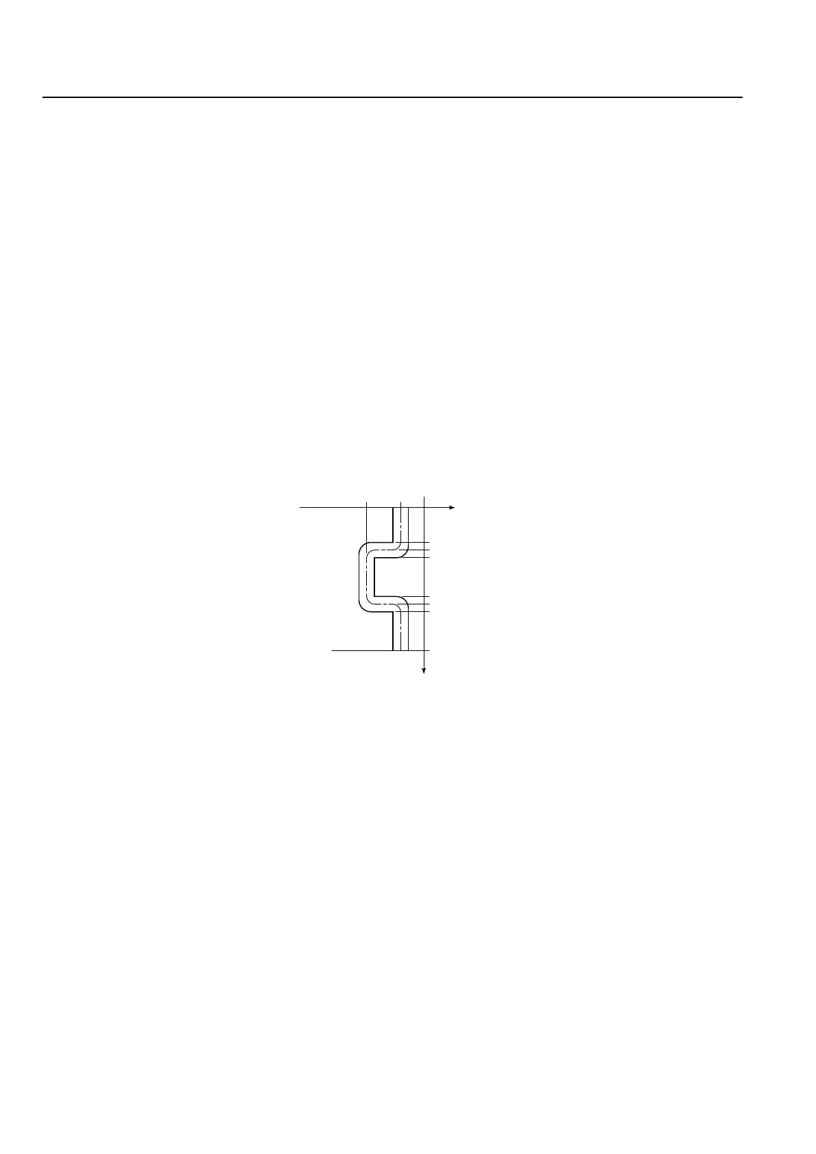
0
−10
−40
95.416
100
(A)
104.583
195.416
200 (B)
204.584
360
Fig. 6
Fig. 6
Z-Axis (mm)
Eje Z (mm)
C-Axis ( °)
Eje C ( °)
 Loading...