Page 7-4
Troubleshooting
INTER-TEL
®
AXXESS
®
MANUAL VERSION 11.0 – May 2008
Circuit Card LEDs
NOTE: A blinking LED indi-
cates that an overly high volt-
age has been detected. A lit
LED merely indicates that there
is some voltage present (as
shown in the table at the right);
it does not, however, indicate
whether the voltage level is
acceptable. To determine the
exact voltage level present, per-
form step 5b.
b. Measure the following system voltages as outlined on page 3-83 or page 3-92. A
digital voltmeter of ±0.5% accuracy is required. Insert the “common” voltmeter
probe into the ground point and insert the other probe into the desired voltage test
point. (See Figure 3-39 on page 3-79 or Figure 3-43 on page 3-88 for voltage test
point locations.)
6. Perform one of the following steps:
• If the system voltages are not within the specified limits, replace the defective
power supply unit.
• If the system voltages are correct and the CPU ACTIVE LED is still flashing, try
another card.
NOTE: If possible, use the save/restore program to save the customer's database
before replacing the CPC or CPU Card (see page 6-65). It can then be restored
(loaded) into a new CPC or CPU Card if necessary. Make sure that the database
back-up battery on the CPC or CPU Card has a charge of at least 3.3VDC and that
the battery back-up jumper strap is in the ON position.
• If the system voltages are correct and the CPU ACTIVE LED is properly lit, yet
the problem still persists, contact Technical Support for assistance.
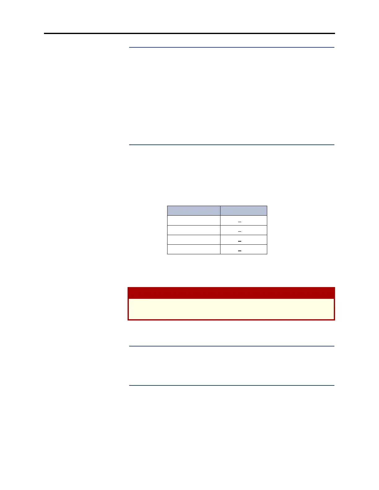
Table 7-1. Voltage Test Point
Voltage Tolerance
-5VDC +
5%
+5VDC +
5%
+24VDC +
5%
SLPWR (+24VDC) +
5%
CAUTION
DO NOT attempt to adjust the power supply voltages. Damage caused by unau-
thorized voltage adjustment will not be covered by the warranty.
Voltage LED Output
+5VDC
OFF
ON
BLINKING
1V
>1V & <6.5V
6.5V
-5VDC
OFF
ON
BLINKING
-1V
<-1V & >-6.6V
-6.5V
+24VDC
OFF
ON
BLINKING
1V
>1V & <29V
29V