Page 3-193
Installation
INTER-TEL
®
AXXESS
®
MANUAL VERSION 11.0 – May 2008
Optional Personal Computer Data Port Modules (PCDPMs)
INSTALLATION
3
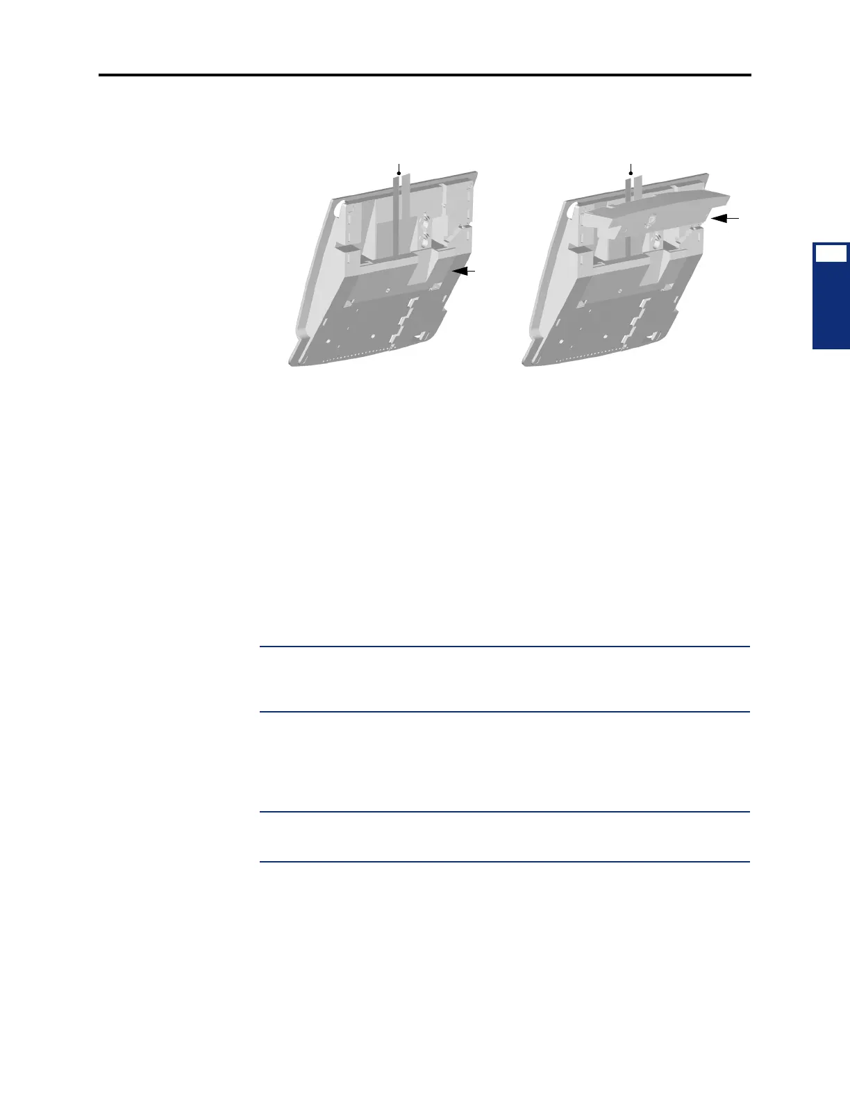
6. Place the cables flat against the phone and carefully place the foot over the cables, as
shown below on the right. For sample display phone PCDPM cable connections, see
Figure 3-88 on page 3-201.
13.23 Install the PC Data Port Module for a Model 8520 or 8560 Phone as outlined below. For
diagrams of the installation, see Figure 3-89 on page 3-202 and Figure 3-90 on page 3-203.
1. Unplug the line cord and headset from the modular jacks on the back of the phone.
2. Open the phone’s base to its fully-extended position.
3. Gently slide the access panel off the phone to expose the PCDPM pin connector (J10)
on the phone’s control board.
4. Align the PCDPM’s J3 connector with the board’s J10 connector and plug the PCDPM
into place on the phone’s board (see page 3-202).
5. If a DSS/BLF Unit (or a PC/output device) is attached to the PC Data Port Module,
attach one end of a PCDPM-to-DSS interface cable (or PCDPM-to-RS232 interface
cable) to the 10-pin (J2) connector on the module, as shown in Figure 3-89. (The other
end of the cable is later attached to the DSS/BLF Unit [or PC/output device] after it is
installed.) For complete RS232 cable pinout requirements, see page 2-99.
NOTE: If the correct end of the cable is not connected into J2, the attached device
does not function properly. Make sure that the notched side of the cable’s plastic con-
nector is facing away from the PCDPM board and that the smooth side lies flat against
it.
If a Modem Data Port Module is attached to the PC Data Port Module, plug the appro-
priate end of the PCDPM-to-MDPM interface cable into the 14-pin (J1) MDPM con-
nector on the PCDPM. (The other end of the cable is later attached to the MDPM after
it is installed.)
NOTE: If the correct end of the cable is not connected into J1, the attached device
does not function properly. Make sure that the notched side of the cable’s plastic con-
nector faces away from the PCDPM board, and the smooth side lies flat against it.
6.
Carefully thread the cables connected to the PCDPM through the slots on the access
panel. Re-attach the access panel to the phone.
7. Secure the access panel to the PCDPM and the phone using the mounting screw sup-
plied in the PCDPM kit.