Page 3-187
Installation
INTER-TEL
®
AXXESS
®
MANUAL VERSION 11.0 – May 2008
Wall Mounting Model 8500, 8520, and 8560 Phones
INSTALLATION
3
13.13 To wall mount the Model 8000 digital phones that have release buttons located on
the bottom housing:
NOTE: The following instructions apply to phones that have release buttons located on the bot-
tom housing of the phone. To disengage the locking mechanism in the base, push in both but-
tons. To lock the base in position, release the buttons.
1.
Close the base completely so that it lies flat against the phone. (Rivet hole 1 on the base
aligns with the rivet hole on the bottom housing of the phone.)
2. Plug the four-inch line cord into the jack on the back of the phone and thread the line
cord through the wall-mount knockout on the base.
3. Insert one of the plastic rivets in rivet hole 1 on the base (see illustration above) and
press it into the rivet hole on the phone. This locks the base to the phone.
4. Test the base to verify that it is securely locked to the phone.
5. Re-attach the metal plate to the phone base.
6. Insert the two plastic rivets through the metal plate and press them firmly into the holes
on the base of the endpoint. This locks the metal plate to the base.
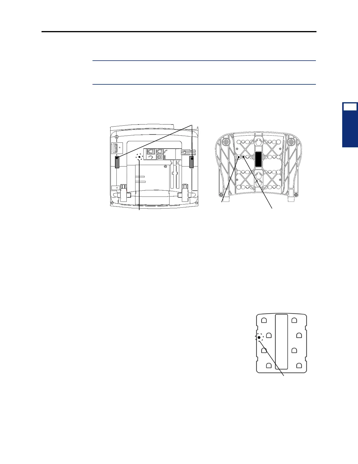
7. Insert the remaining plastic rivet through rivet hole 3 (as
shown at right) in the metal plate and press it firmly into
rivet hole 2 in the base. This locks the metal plate to the
base.
8. Plug the line cord into the jack on the wall-mount bracket
and position the phone securely on the wall-mount
bracket.
9. Flip the handset hanger down to the horizontal position
and lock it into place. This holds the handset in place.
Rivet Hole
Base
Rivet Hole 1
Release Buttons
Bottom Housing
(Base not shown)
Rivet Hole 2
(Used to lock metal plate to base)
(Used to lock base to bottom housing)