Page 3-213
Installation
INTER-TEL
®
AXXESS
®
MANUAL VERSION 11.0 – May 2008
Hardware Installation
INSTALLATION
3
NOTE: The first VPC must be installed so that it can be connected to the far end
of the AIC-to-VPC interface cable that was previously attached to the AIC.
b.
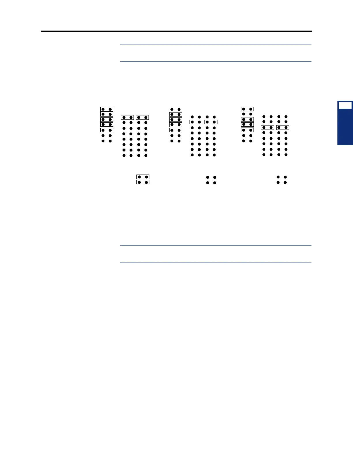
Depending on which number VPC (1-3) is being installed, check to make sure that
jumper straps are installed in the following locations on the VPC (see Figure 3-98
on page 3-222 for orientation).
c. Insert the VPC in the appropriate slot and attach it to the chassis using the screw
previously removed. Make sure the card is securely attached to the PC Mother-
board and does not touch any adjacent cards.
d. Attach the next available connector on the AIC-to-VPC interface cable to the 40-
pin connector on the VPC. (One end of the cable was previously attached to the
40-pin connector on the AIC.)
NOTE: Be sure that the colored edge of the AIC-to-VPC interface cable aligns
with pin 1 on the connector.
6.
If not already installed, install the Video Card as follows:
a. Remove the bracket that covers the opening to the appropriate 8-bit (half-size) slot
as shown in Figure 3-96 on page 3-220, and set the bracket and screw aside.
b. Insert the Video Card in the appropriate slot and attach it to the chassis using the
screw removed in step 6a. Make sure the card is securely attached to the PC Moth-
erboard and does not touch any adjacent cards.
7. If desired and if not already installed, install the optional Fax card. There are two dif-
ferent styles of fax cards. The settings for both fax cards are the same, but the location
and labeling of the DIP switches and jumper settings have been rearranged. (See Figure
3-100 on page 3-224 for the older-style cards and see Figure 3-101 on page 3-225 for
the newer-style fax cards.):
a. Remove the bracket that covers the opening to the appropriate 16-bit (full-size)
slot, and set the bracket and screw aside. (See Figure 3-96 on page 3-220 for a
sample card slot arrangement.)
b. Ensure that the IRQ selection jumper (J503 on 2-, 4-, and 8-port cards; J902 on
12-port cards; and J2502 on 16-port cards) is installed in location IRQ9.
FIRST VPC INSTALLED SECOND VPC INSTALLED
(300 HEX)
W3
(HIGHWAY 0)
W2
W1
(308 HEX)
W3
(HIGHWAY 1)
W2
W1
(CLOCK TERMINATED)
W4
(NOT TERM.)
W4
THIRD VPC INSTALLED
(310 HEX)
W3
(HIGHWAY 2)
W2
W1
(CLOCK NOT TERMINATED)
W4