Installation
INTER-TEL
®
AXXESS
®
MANUAL VERSION 11.0 – May 2008
Page
3-214
Hardware Installation
c. Ensure that the eight address selection DIP switches (SW1 on 2-, 4-, 8-, and 12-
port cards and SW2501 on 16-port cards) are set to 320:
– 1-3 & 5-6 = ON for older cards (down); 4 & 7-8 = OFF for older cards (up).
– 1-3 & 5-6 = CLOSED for newer cards (down); 4 & 7-8 = OPEN for newer
cards (up).
d. Ensure the two MVIP clock termination DIP switches (SW2 on 2-, 4-, and 8-port
cards; SW1001 on 12-port cards; and SW2601 on 16-port cards) are set in the
OFF (up) position.
e. Insert the Fax Card in the appropriate slot and attach it to the chassis using the
screw removed in sub-step a. Make sure the card is securely attached to the PC
Motherboard and does not touch any adjacent cards.
f. Attach the next available connector on the AIC-to-VPC interface cable to the 40-
pin connector on the Fax Card. (One end of the cable was previously attached to
the 40-pin connector on the AIC.)
NOTE: Be sure that the colored edge of the AIC-to-VPC interface ribbon cable
aligns with pin 1 on the connector.
8.
Replace the cover on the PC and re-install the screws.
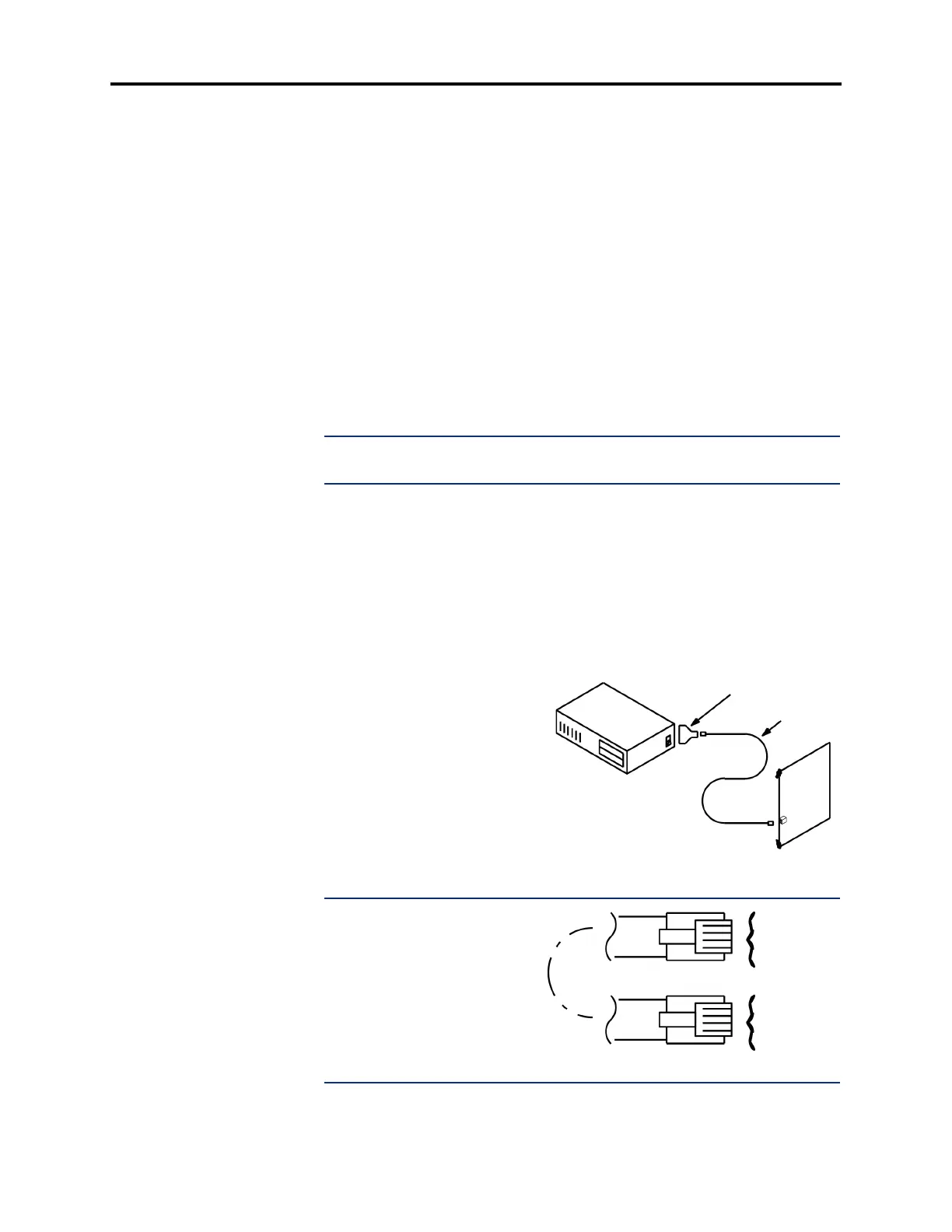
9. To set up the RS232 interface between the phone system and the Voice Processing PC:
a. Referring to the diagram below, attach the DB9 modular adapter (part no.
804.2420; supplied with the PC) to the DB9 (COM1) serial port connector on the
PC.
b. Plug one end of the mod-to-mod line cord – part no. 813.1592 [DMS67 in
Europe]; supplied with the PC, into the DB9 modular adapter.
c. Plug the other end of the line
cord into an RS-232 port on the
CPC or CPU Card. Do not use
the Options Card.
NOTE: The RS232 interface
consists of a standard, two-pair,
reversing, mod-to-mod line cord
with an attached 9-pin modular
adapter. A reversing line cord
can be identified by examining
the modular plug connectors
side-by-side as shown at the
right.
DB9 ADAPTER
LINE CORD
VOICE PROCESSING PC
CPC128 OR
CPU020/PCM CARD
TWO-PAIR REVERSING LINE CORD
YELLOW
GREEN
RED
BLACK
BLACK
RED
GREEN
YELLOW