Send documentation comments to mdsfeedback-doc@cisco.com
48-16
Cisco MDS 9000 Family Fabric Manager Configuration Guide
OL-17256-03, Cisco MDS NX-OS Release 4.x
Chapter 48 Configuring FCIP
Using the FCIP Wizard
Step 6 Modify the optional TCP parameters, if desired. Refer to Fabric Manager Online Help for explanations
of these fields.
Step 7 (Optional) Click the Tunnels tab and modify the remote IP address in the Remote IPAddress field for
the endpoint to which you want to link.
Step 8 Enter the optional parameters, if desired. See the Cisco MDS 9000 Family CLI Configuration Guide for
information on displaying FCIP profile information.
Step 9 Click Apply Changes icon to save these changes.
Creating FCIP Links
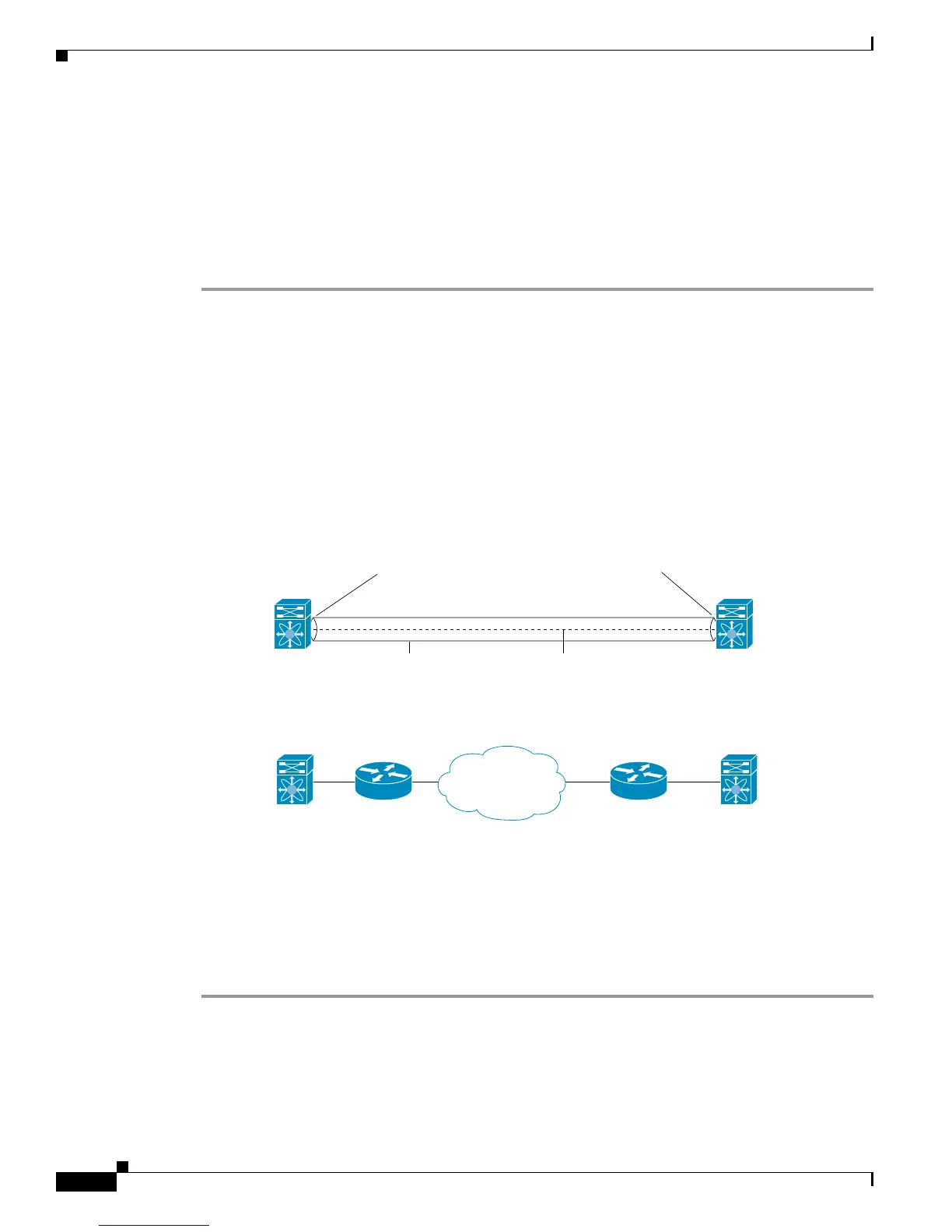
When two FCIP link endpoints are created, an FCIP link is established between the two IPS modules or
MPS-14/2 modules. To create an FCIP link, assign a profile to the FCIP interface and configure the peer
information. The peer IP switch information initiates (creates) an FCIP link to that peer switch (see
Figure 48-19).
Figure 48-19 Assigning Profiles to Each Gigabit Ethernet Interface
Verifying Interfaces and Extended Link Protocol
To verify the FCIP interfaces and Extended Link Protocol (ELP) on Device Manager, follow these steps:
Step 1 Make sure you are connected to a switch that contains an IPS module.
Step 2 Select FCIP from the Interface menu.
Step 3 Click the Interfaces tab if it is not already selected. You see the FCIP Interfaces dialog box.
Switch 1
FCIP link
Switch 1
Switch 2
Switch 2
IP router
IP router
91562
IP
network
IP address of Gigabit Ethernet
interface 3/1 = 10.100.1.25
IP address of Gigabit Ethernet
interface 3/1 = 10.1.1.1
Endpoint
Interface FCIP = 51
Profile = 10
Connecting switch (peer) = 10.1.1.1
Virtual (E) ISL
Endpoint
Interface FCIP = 52
Profile = 20
Connecting switch (peer) = 10.100.1.25
 Loading...