Send documentation comments to mdsfeedback-doc@cisco.com
18-4
Cisco MDS 9000 Family Fabric Manager Configuration Guide
OL-17256-03, Cisco MDS NX-OS Release 4.x
Chapter 18 Managing System Hardware
Power Supply Configuration Modes
Note In a Cisco MDS 9500 Series switch, power usage is reserved for both supervisors whether one or both
supervisor modules are present.
Power Supply Configuration Modes
Switches in the MDS 9000 Family have two redundant power supply slots. The power supplies can be
configured in either redundant or combined mode.
• Redundant mode—Uses the capacity of one power supply only. This is the default mode. In case of
power supply failure, the entire switch has sufficient power available in the system.
• Combined mode—Uses the combined capacity of both power supplies. In case of power supply
failure, the entire switch can be shut down (depends on the power used) causing traffic disruption.
This mode is seldom used, except in cases where the switch has two low power supply capacities
but a higher power usage.
Note The chassis in the Cisco MDS 9000 Family uses 1200 W when powered at 110 V, and 2500 W when
powered at 220 V.
To configure the power supply mode, follow these steps:
Step 1 In the Fabric Manager Physical Attributes pane, expand Switches and then select Hardware. Click the
Power Supplies tab.
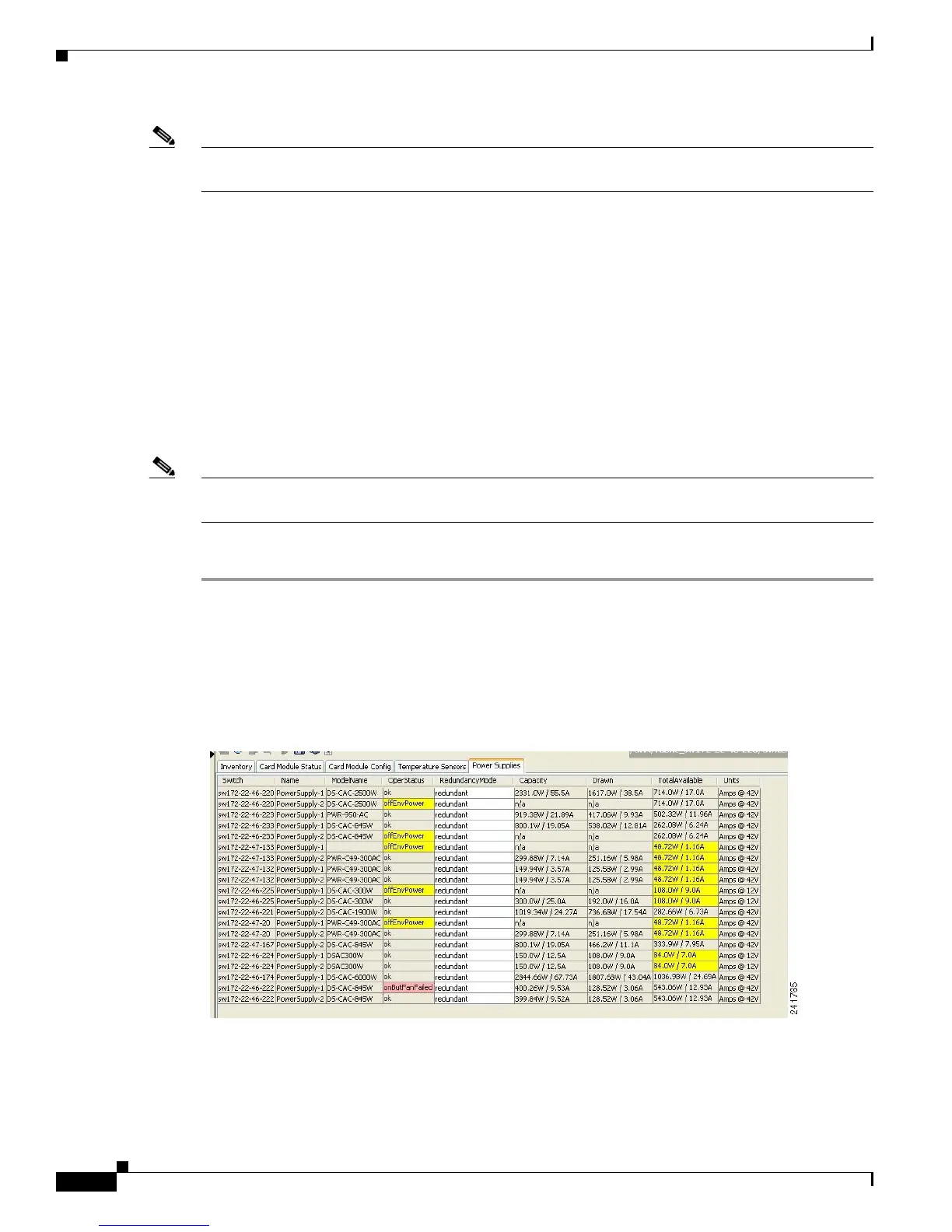
You see the power supply information screen shown in Figure 18-3.
Low TotalAvailable (< 200.0W) values for non-2-slot chassis are highlighted in yellow, as inserting a
new card into the switch requires power around 180 W.
Figure 18-3 Power Supply Information in Fabric Manager
Step 2
In Device Manager, click Physical > Power Supplies.
You see the screen in Figure 18-4.
 Loading...