Send documentation comments to mdsfeedback-doc@cisco.com
18-5
Cisco MDS 9000 Family Fabric Manager Configuration Guide
OL-17256-03, Cisco MDS NX-OS Release 4.x
Chapter 18 Managing System Hardware
Power Supply Configuration Modes
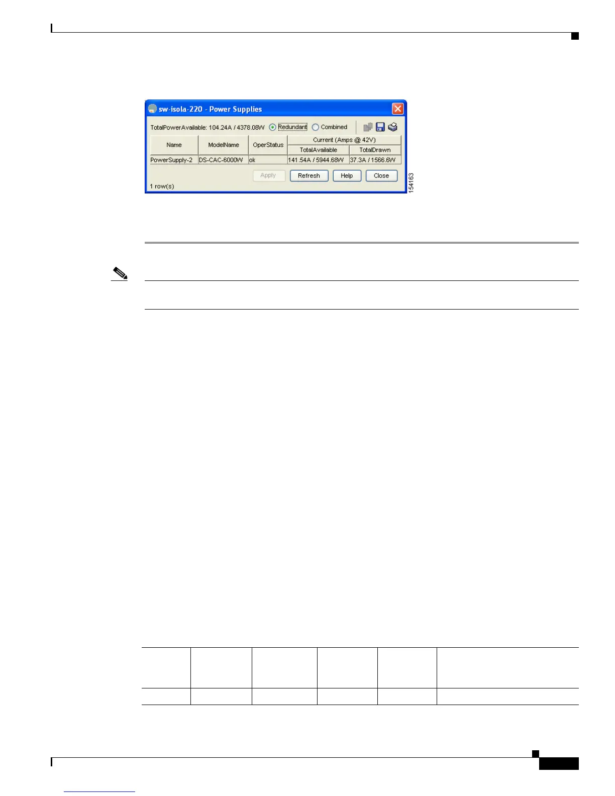
Figure 18-4 Power Supply Information in Device Manager
Step 3
Configure the power attributes for the power supply.
Step 4 Click Apply in Device Manager or click the Apply Changes icon in Fabric Manager.
Note See the “Displaying Power Usage Information” section on page 18-3 to view the current power supply
configuration.
Power Supply Configuration Guidelines
Follow these guidelines when configuring power supplies:
1. When power supplies with different capacities are installed in the switch, the total power available
differs based on the configured mode, either redundant or combined:
a. Redundant mode—The total power is the lesser of the two power supply capacities.
For example, suppose you have the following usage figures configured:
Power supply 1 = 2500 W
Additional power supply 2 = not used
Current usage = 2000 W
Current capacity = 2500 W
Then the following three scenarios will differ as specified (see Table 18-1):
Scenario 1: If 1800 W is added as power supply 2, then power supply 2 is shut down.
Reason: 1800 W is less than the usage of 2000 W.
Scenario 2: If 2200 W is added as power supply 2, then the current capacity decreases to 2200
W.
Reason: 2200 W is the lesser of the two power supplies.
Scenario 3: If 3000 W is added as power supply 2, then the current capacity value remains at
2500 W.
Reason: 2500 W is the lesser of the two power supplies.
Table 18-1 Redundant Mode Power Supply Scenarios
Scenario
Power
Supply 1
(W)
1
Current
Usage
(W)
Insertion of
Power
Supply 2 (W)
New
Capacity
(W) Action Taken by Switch
1 2500 2000 1800 2500 Power supply 2 is shut down.
 Loading...