Send documentation comments to mdsfeedback-doc@cisco.com
29-16
Cisco MDS 9000 Family Fabric Manager Configuration Guide
OL-17256-03, Cisco MDS NX-OS Release 4.x
Chapter 29 Configuring Inter-VSAN Routing
Manual IVR Configuration
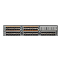
Figure 29-8 Local Topology Tab
Step 2 Click the Local Topology tab to display the existing IVR topology.
Step 3 Click the Create Row icon to create rows in the IVR topology (see Figure 29-8).
Step 4 Select the switch, switch WWN, and a comma-separated list of VSAN IDs for this topology.
Step 5 Click Create to create this new row.
Step 6 Click the Apply Changes icon to create the IVR topology.
Note Repeat this configuration in all IVR-enabled switches or distribute using CFS.
Tip Transit VSANs are deduced based on your configuration. The IVR feature does not have an explicit
transit-VSAN configuration.
Activating a Manually Configured IVR Topology
After manually configuring the IVR topology , you must activate it.
Caution Active IVR topologies cannot be deactivated. You can only switch to IVR topology automatic mode.
To activate the manually configured IVR topology using Fabric Manager, follow these steps:
Step 1 Expand All VSANs and then select IVR in the Logical Domains pane.
You see the IVR configuration in the Information pane.
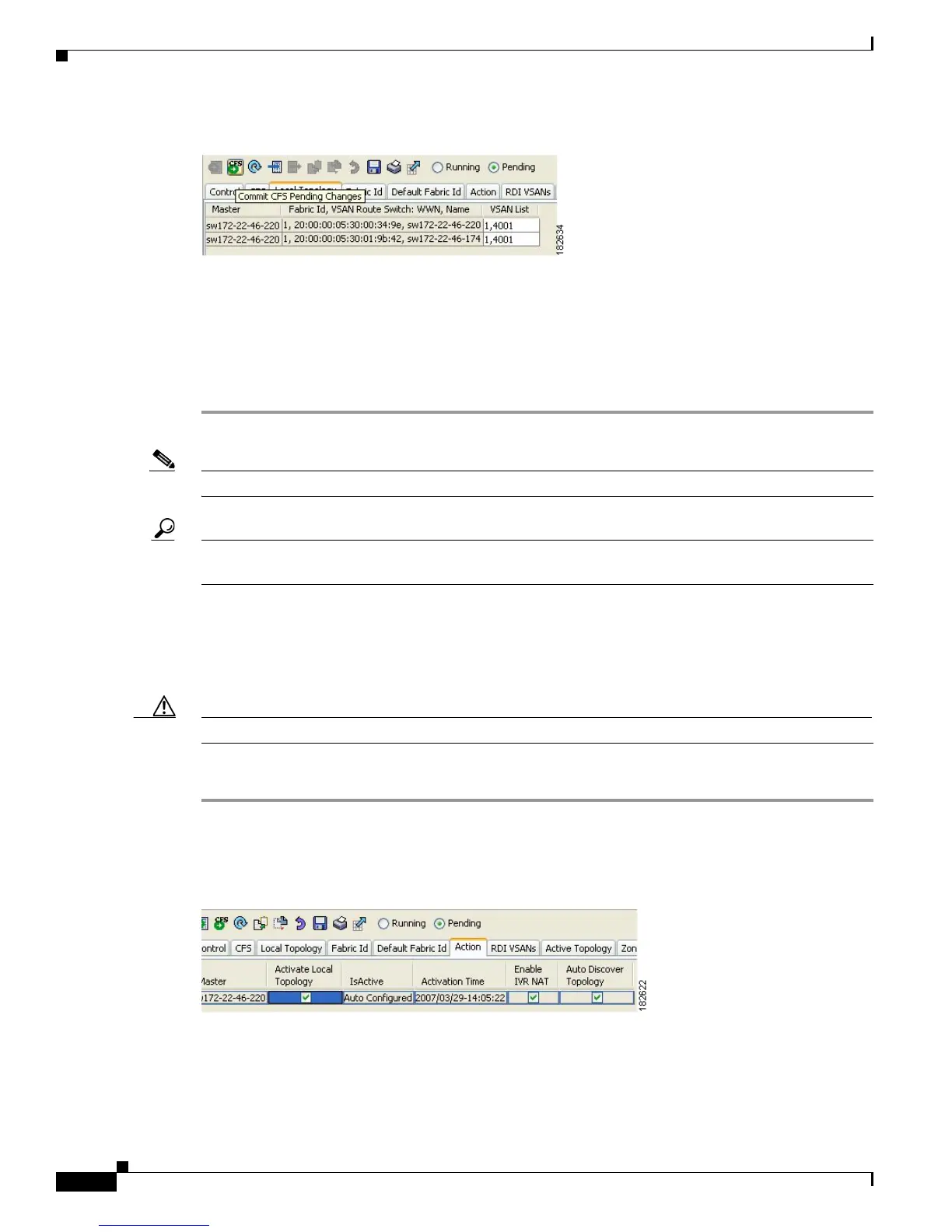
Figure 29-9 Action Tab
Step 2
Click the Action tab to display the existing IVR topology.
Step 3 Check the Activate Local Topology check box (see Figure 29-9).
 Loading...