- 1164 -
Disturbance recorder
A phenomenon of fault occurring will be recorded in the disturbance recorder and its
phenomenon is recorded within 1ms accuracy. The recorder starts when TRC trip command is
issued, but recording will also be started if a relay of the recorder detects an abnormal
phenomenon. The relays of the recorder are such as overcurrent, overvoltage, etc. The recorder,
additionally, will be instructed by PLC function, so an instruction is managed with a setting.
The amount of recording time and the sampling time are adjustable. Therefore, measured
values, such as current voltage and frequency, are recorded in accordance with the amount and
the sampling time. Logic signals are also recorded together with disturbance phenomena. The
recorder can hold up to 256 logic signals. The number of disturbance phenomena to be recorded
is limited by the amount of recording period and the sampling time.
8.3.1 Recording time and amount
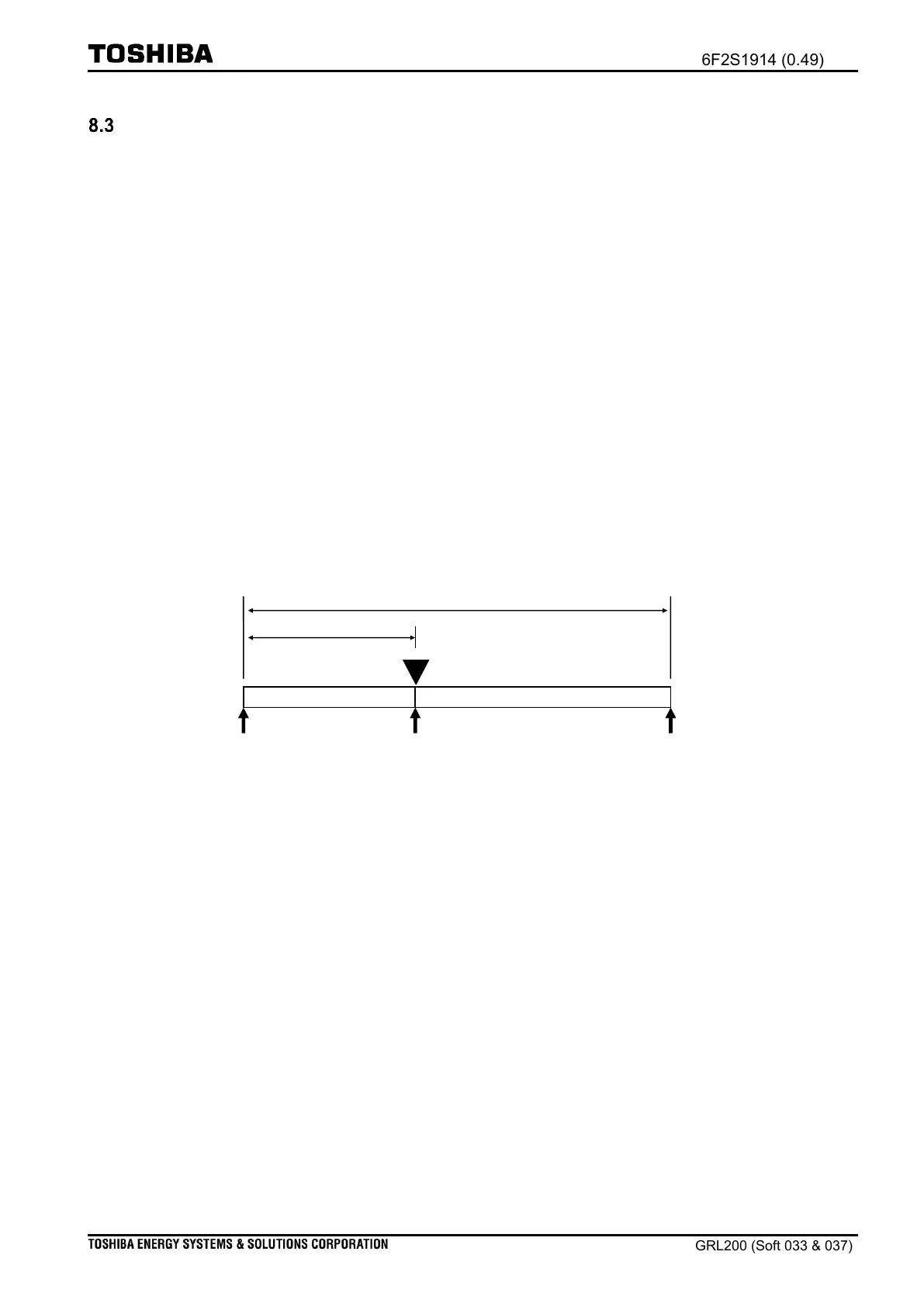
(i) Time settings
Period of the recording is set using the [Record Time]. The disturbance recorder can operate
before the occurrence of the fault; the time before the fault occurrence can be set using the
[Pre-fault Time]. The user can choose a time among 0.1 sec. to 10.0 sec.
Figure 8.3-1 Period of recording time
(ii) Sampling rate setting
Sampling time is defined with setting [Sampling rate]; it can be selected either 7.5 electrical
degrees or 15 electrical degrees. For example, if the user set 7.5 for the [Sampling rate], the
disturbance recorder starts to collect the date in the sampling rate (2400Hz) in 50Hz system.
(iii) Trip command setting
As shown in Figure 8.3-1, the disturbance recorder starts when the trip command is issued,
provided On is set for the [Trip Trig.Sw]. The user has to set Off for the setting, if the
disturbance recorder shall not start with the trip command.
8.3.2 Relays within disturbance recorder
Four relays are provided in the disturbance recorder exclusively: OC-DRT, EF-DRT, UV-DRT,
and UVS-DRT relays.

 Loading...


