- 153 -
source does not exist behind busbar B. Accordingly, as for the fault on the line AB, the user
should have underreach setting in enough to the zone1
(S)
.
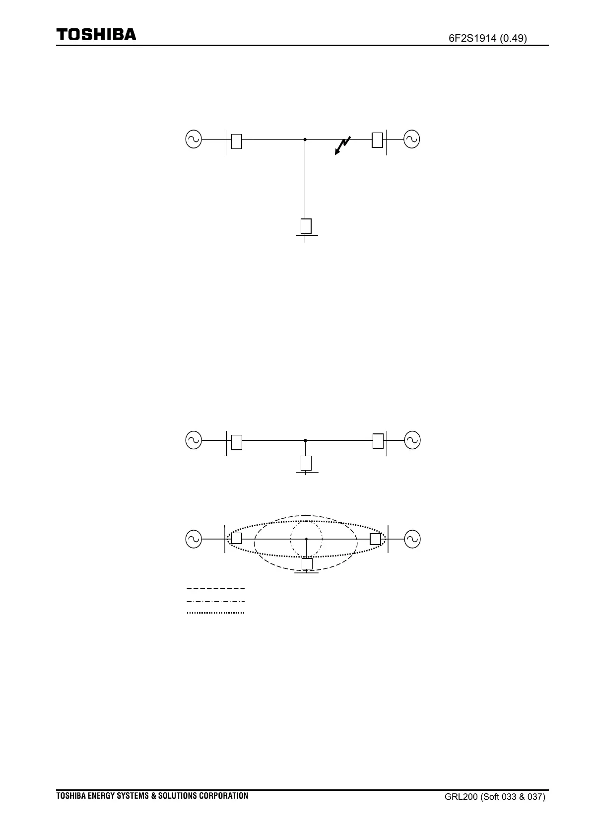
Figure 2.10-58 Line CJ tapped at junction J
(iii) Setting for the primary zone (Zone1 and a short tapped line)
Suppose the busbar C is tapped at the junction J on the line AB, as shown in Figure 2.10-59.
It is required to have the reach setting in both the zone1(S) and the zone1(U) so as to hold a
part of the entire length of the line as shown in the long-dashed-short-dashed -circle line to
avoid unwanted operations for external faults at busbar C. Consequently, clearing faults by a
delayed zone2 are performed mostly, as shown in the broken-circle line that is operated at an
end of the line AB†.
long-dashed-short-dashed-circle line
Figure 2.10-59 Short line CJ tapped at junction J
†Note: To solve the problem, we recommend using the distance carrier command
protection or the current differential protection for the multi-terminals line shown
in the dotted-circle line.

 Loading...


