- 326 -
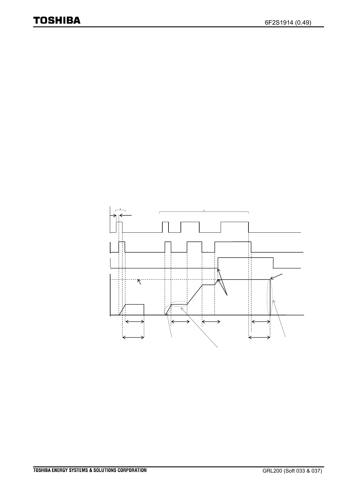
operation time. The UV1 element has a time counter that increases in response to the fault
occurrence and duration. This figure also shows the increment degree of the time counter for
the fault occurrences.
As for an intermittent fault (the former in the figure), the time counter does not reach
the trip level. In the other word, the UV1 element will be paralyzed in the reset time [TUV1R].
If a series of fault occurs, the time counter increase corresponding to the duration of series
faults. When the time counter reaches the trip level, then the UV1 element issues a trip signal
after a certain delay. After issuing the trip signal, if a series of fault disappears completely, the
operation of the UV1 element is expired after the reset time [TUV1R].
When the user requires resetting the operation of the UV1 element immediately, setting
zero for the settings [TUV1R] is needed. Consequently, when a voltage is recovered over the
reset threshold (drop-off), the operation of the UV1 element is reset promptly.
Figure 2.24-3 Faults occurrences and reset operation when IDMT being applied
2.24.3 Miscellaneous functions
(i) Blocking UV operation
Blocking the UV function may be required when a failure in the voltage transformer occurs.
In this case, the user shall set Block for scheme switch [UV1-VTFBlk]. Non (as a default) is set
for scheme switch [UV1-VTFBlk] in order that the UV function is not blocked by the failure.
(ii) UV trip signal
The UV1 element issues a trip signal for the trip circuit (TRC†) when Trip is set for scheme
Condition fault occurrence
Fault observation by the relay
Incrimination of time counter
corresponding to the fault
duration.
T
1
: Resetting time set by the user
T
2
: Actual resetting time in the relay operation
T
3
: Time gap between fault occurrence and relay start time
Increment process in time
counter
Value maintenance of time counter

 Loading...


