- 343 -
2.26.2 DFRQ features and characteristics
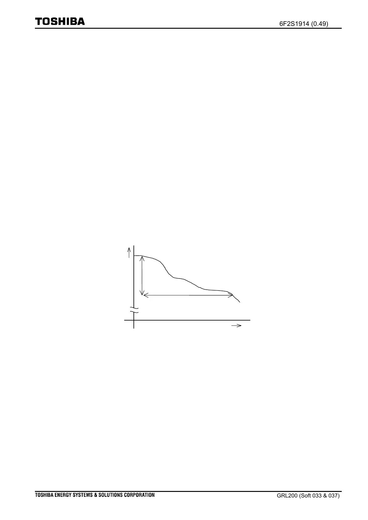
(i) RISE/DOWN characteristic
The RISE and DOWN elements calculate the gradient of frequency-change (Δf/Δt) every
5msec. Figure 2.26-3 shows how to calculate the gradient using Δf and Δt: the change of
frequency (Δf) over a time interval and Δt equals to 100ms. Six elements are provided for the
DFRQ function; each element can operate independently. Each stage of the DFRQ function
issues a trip signal if Δf exceeds the setting value of 50 consecutive times.
The user can set the state 1 to detect whether a frequency to be rising or to be descending
using scheme switch [DFRQ1-Chara]. For example, when Rise is set for the scheme switch
[DFRQ1-Chara], the DFRQ examines the gradient of frequency-change (Δf/Δt) in up.
Conversely, when Down is set for the scheme switch, the DFRQ examines the gradient of
frequency-change (Δf/Δt) in down. Setting [DFREQ1] is used to configure an operation
threshold; the operation threshold is configured with Hertz per second.
The operation of the RISE/DOWN elements is blocked when the FRQBLK element runs.
That is, if an obtained voltage is below the setting [FRQBLK], any operation of the DFRQ
function is blocked. The FRQBLK element is discussed in section 2.26.1(i).
Figure 2.26-3 Gradient of frequency rate-of-change
(ii) Enabling DFRQ function
The user should set On to enable the DFRQ function using scheme switch [DFRQ1-EN]. If the
user is not to operate the DFRQ function, Off should be set for the scheme switch.
(iii) DFRQ trip signal
The DFRQ can issue a trip signal for the function of trip circuit (TRC) when Trip is set for
scheme switch [DFRQ1-UseFor]. However, when an alarm signal is required in place of the
trip signal, the user should set Alarm for scheme switch [DFRQ1-UseFor]. The TRC function
is discussed separately. (See Chapter
Relay application: Trip circuit
)

 Loading...


