- 648 -
user-programmed logic is connected internally to the signal “Operate completed”,
hence this signal is now generated by the user-programmed logic at connection
point # 2 “user- configurable condition”. That is, set the scheme switch [SPOS01-
LGCFEXOT] to PLC and use “SPOS01IN_TMP_42”.
Output signal to BO
The SPOS01 function, in Figure 4.1-26, can issue a signal “Operate” at the output point
“SPOS01_FEX_BO”, when the SPOS01 function determines that the input signal “Local-Off-
Control” is true.
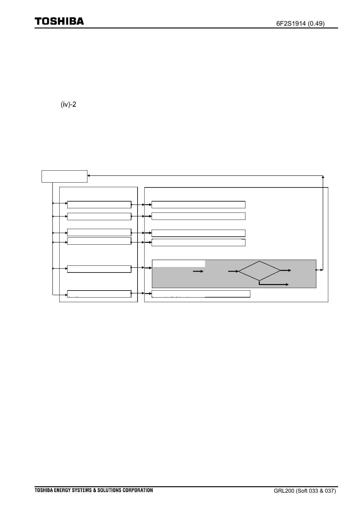
(v) Receiving “operate command On” using the PLC function
Operate command Off control from front-panel
Operate command Off control from remote-end
Operate command Off control
by PLC function
Select command Off from remote-end
Select command On from remote-end
Select command Off from front panel
Select command On from front panel
Select command On by the PLC
function
Select command Off by the PLC
function
Operate command On from the remote-end
Operate command On control from front-panel
PLC logic programmed
by the user
On control by PLC function
Figure 4.1-27 Outline of operate command for ‘On’
Figure 4.1-27 outlines the reception of the operate command ‘On’ with the PLC function; it
describes the operate logic when an “Operate command On (PLC-On Control)” signal is
generated by the PLC function. There are two input points for reception of this command signal,
unlike the signal “operate command closing” (PLC-On Control).; the former connection point
(PLC#3) is used for the reception of the operate-command requiring the interlock check, the
latter connection point (PLC#4) is used or the reception of the operate-command not requiring
interlocking check. That is, for the SPOS01 function, when the user wishes to apply for the
operate logic the signal “Operate command On (PLC-On-Control)” generated in the user-
programmed logic and when the interlock check is required in the operate logic, apply the
signal at the connection point (PLC#3; is DEV01_CL_COMMAND). Alternatively, if the
interlock check is not required, apply the signal at the other connection point (PLC#4 i.e.
DEV01_CL_INTERLOCK); The PLC#3 and PLC#4 is denoted as the PLC#1 and PLC#2 in
Table 4.1-2. Note that the user should set PLC for scheme switch [SPOS01-LGCTRCON].

 Loading...


