- 806 -
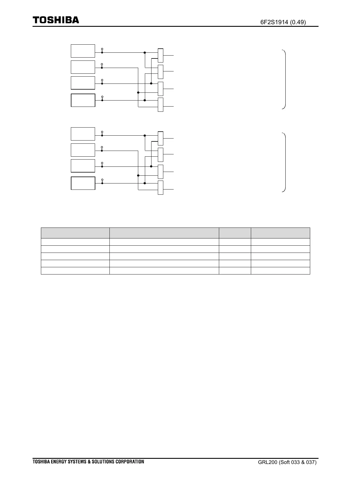
DRLI1: Running-line out-of-service & Incoming-line in-service
DRDI1: Both Running-line and Incoming-line out-of-service
LRDI1: Running-line in service & Incoming-line out-of-service
LDLI1: Both Running-line and Incoming-line in-service
Figure 4.6-8 Line-outage check logic in SYNCHK_Ry1
DRLI2: Running-line out-of-service & Incoming-line in-service
DRDI2: Both Running-line and Incoming-line out-of-service
LRDI2: Running-line in service & Incoming-line out-of-service
LDLI2: Both Running-line and Incoming-line in-service
Figure 4.6-9 Line-outage check logic in SYNCHK_Ry2
Table 4.6-5 Voltage condition settings in SYNCHK1
Voltage check timer (LRDI, DRLI)
Voltage check timer (DRDI)
(ii) Check logic and settings
Figure 4.6-10 shows the SYNCHK1 logic. When the DPSY01 function confirms the reception
of a selection-command, the DPSY01 function issues a “DPSY01_OSE_RCV” signal to the
SYNCHK1 function. Then the SYNCHK1 function commences with the check for the voltage
condition by introducing the results of the SYNCHK_Ry function. As described previously, four
voltage conditions are considered, the user should select the voltage-conditions required by the
application. The SYNCHK1 logic provides two permissive signals: “SYNC01_SLD_VCS” signal
and “SYNC01_SYN_CLC” signal.

 Loading...


