- 1504 -
PWS alarm threshold setting
The IED has power supply module (PWS) at the far left slot. The user can confirm DC rated
voltage on the hardware nameplate by checking the cord at Positions ‘8’, but the user should
select either alarm thresholds for dropping DC voltage by inserting a jumper on the PWS
(Figure 13.5-1). See
Section Power supply module
in
Chapter Technical description
.
DC rated voltage, e.g., 1=’110 to 250Vdc’, selected by the ordering
Figure 13.5-1 Alarm threshold set on PWS module
CAUTION
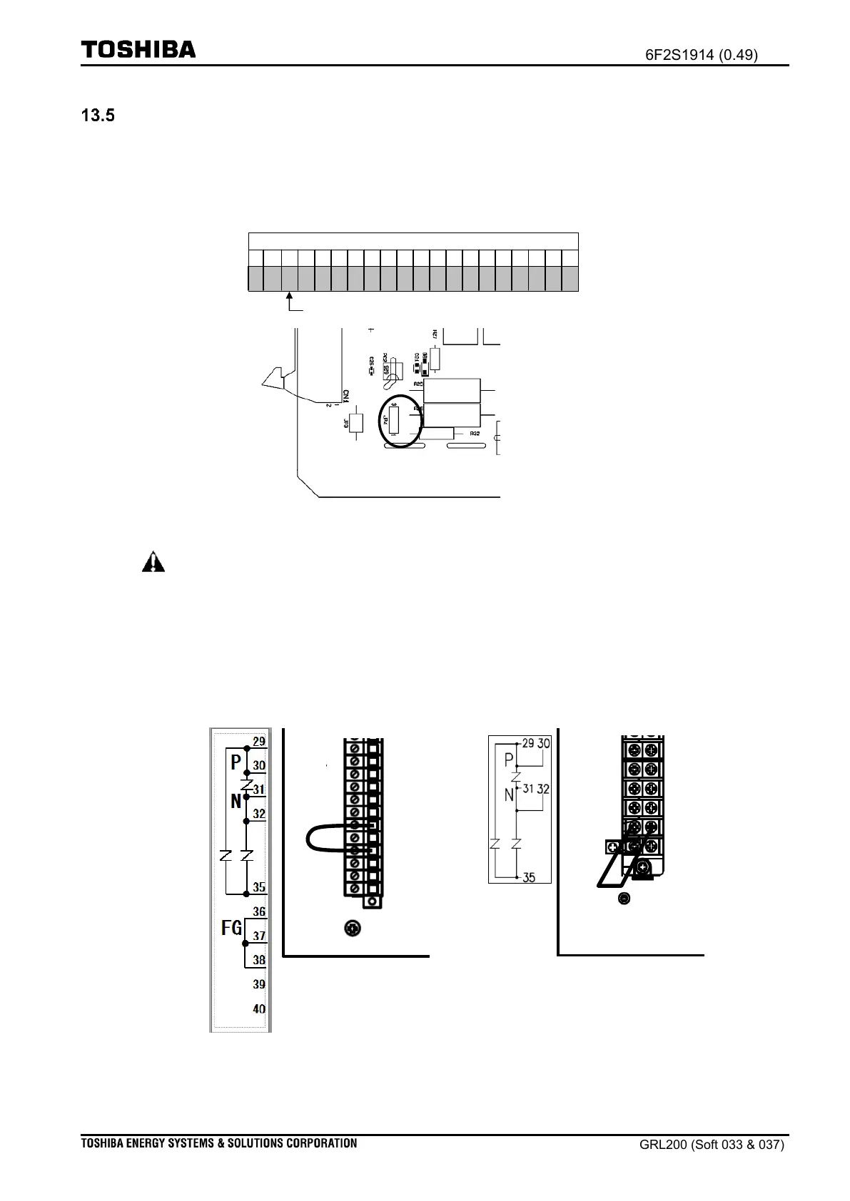
Note: A short-wire is connected between terminal screws No. 35–37 ( No.35–36 for type
using the ring terminal). It is done by the manufacturer. The user shall remove
that when the user undertakes the dielectric voltage test for the IED; and the user
shall connect again the terminals with that after the test (See
Appendix: Notes for
the dielectric voltage test
).
Type using compression terminals
Type using ring terminals
29
30
31
32
33
34
35
36
37
38
39
40
Figure 13.5-2 PWS terminal labels

 Loading...


