- 654 -
4.1.4 Setup for BIO module
The user should connect the SPOS input/output points with the BI and the BO circuits;
subsequently, the SPOS function is able to issue select and operate commands. The user should
execute the following four steps below.
i BI connection for status-signals
ii BO connection for “Select command On/Off”
iii BO connection for “operate command”
iv Contact health check
Note that the SPOS01 function commences operation when the scheme switch [SPOS01-EN]
is set to On.
(i) BI connection for status-signals
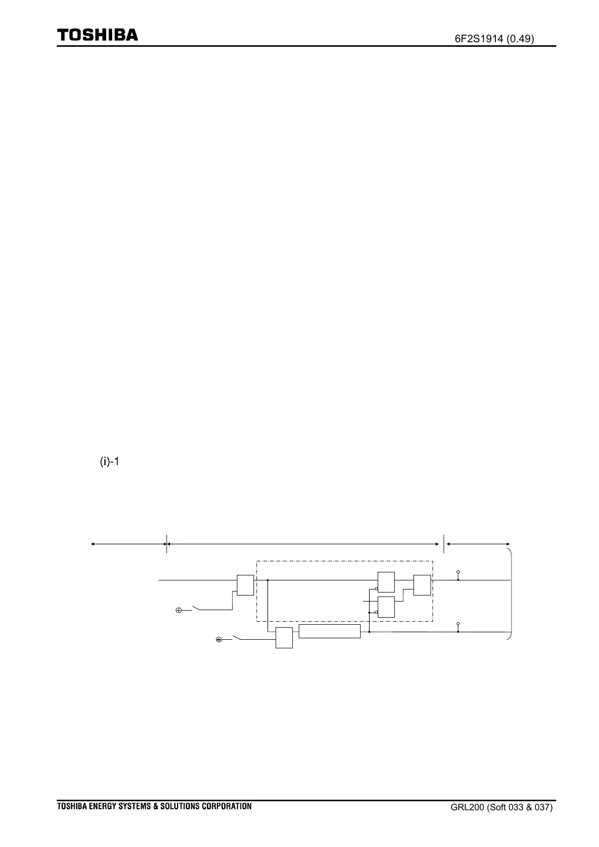
Figure 4.1-30 exemplifies the reception of signals at the SPOS01 function; the user can set a
input-point using the setting [SPOS01-NOPSG]†.
†Note: Normally an input-signal corresponding to phase-A is generated using a normally-
open contact (NO). If the signal is generated by the normally-closed contact, the
user is required to set scheme switch [SPOS01-NSOSGI] On in order that the
input-signal should be decided in inversion.
Connection with Binary input circuit
Suppose an input signal is provided on the first BI circuit at IO#1 slot. In this case, the user
should set the input point (200B01 8001001110†) for the setting [SPOS01-NOPSG], otherwise,
the SPOS01 function cannot run correctly.
Signals by Binary input circuits
Signal acquisition logic in SPOS01
“SPOS01_F_QLT_SPP”
(510001_8101011F59)
Event suppression detector
BI signal connected by
setting [SPOS01-NOPSG]
“SPOS01_STATE”
(510001_0001011001)
To select and operate
condition logics
Figure 4.1-30 Acquisition of binary input signal in SPOS01
†Note: The user should set the actual input-points. For Input points see in Chapter
Technical description: Binary IO module
.
‡Note: In Figure 4.1-30 two signals can be issued: “SPOS01_STATE” and
“SPOS01_F_QLT_SPP”. One is used in the select condition logic and the operate
condition logic (see Figure 4.1-13 and Figure 4.1-29). Another is used for operation

 Loading...


