- 1495 -
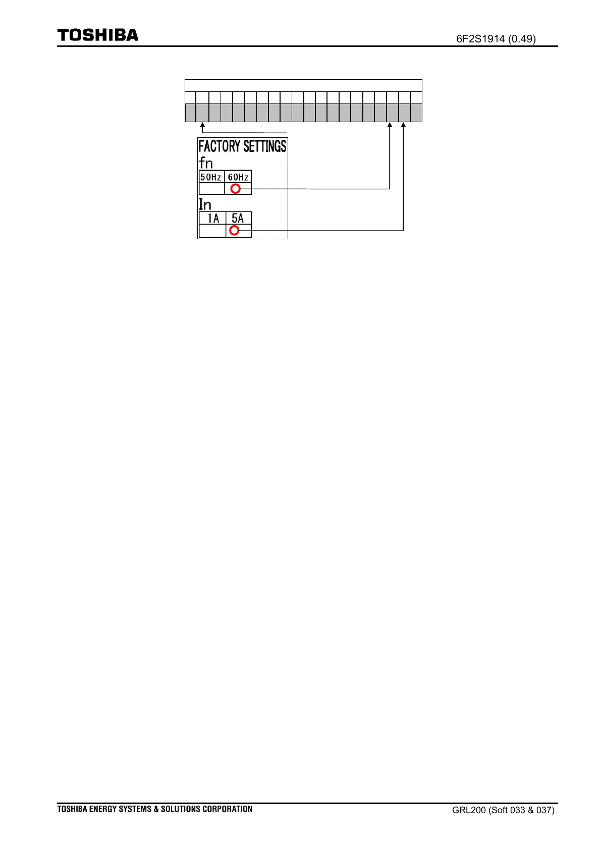
System frequency (fn) = 60Hz
Figure 13.3-2 Factory setting example
Note: The user can also change a rated current (In). To change it, see succeeding section
Changing rated current
.
The user is not able to change the system frequency (fn).
(iii) Combination of VCT and BIOs
Transformer module (VCT) is located at the far right slot (e.g., at ‘VC1’ in Figure 13.3-3).
Identify the code at Position ‘7’ to read the VCT type (e.g., VCT11B is mounted when Figure
13.3-2 is true).
The user can check the layout of the binary input and output modules (BI, BO, or BIO)
using the ordering codes. For example, the user can find BI3A and BO1A modules in an IED
depending on the ordering cord “4H” at Positions A&B. The user can also read the
configuration with IO configuration label. Additionally, the user can check terminal block types
by seeing a code at Positon ‘H’.

 Loading...


