- 121 -
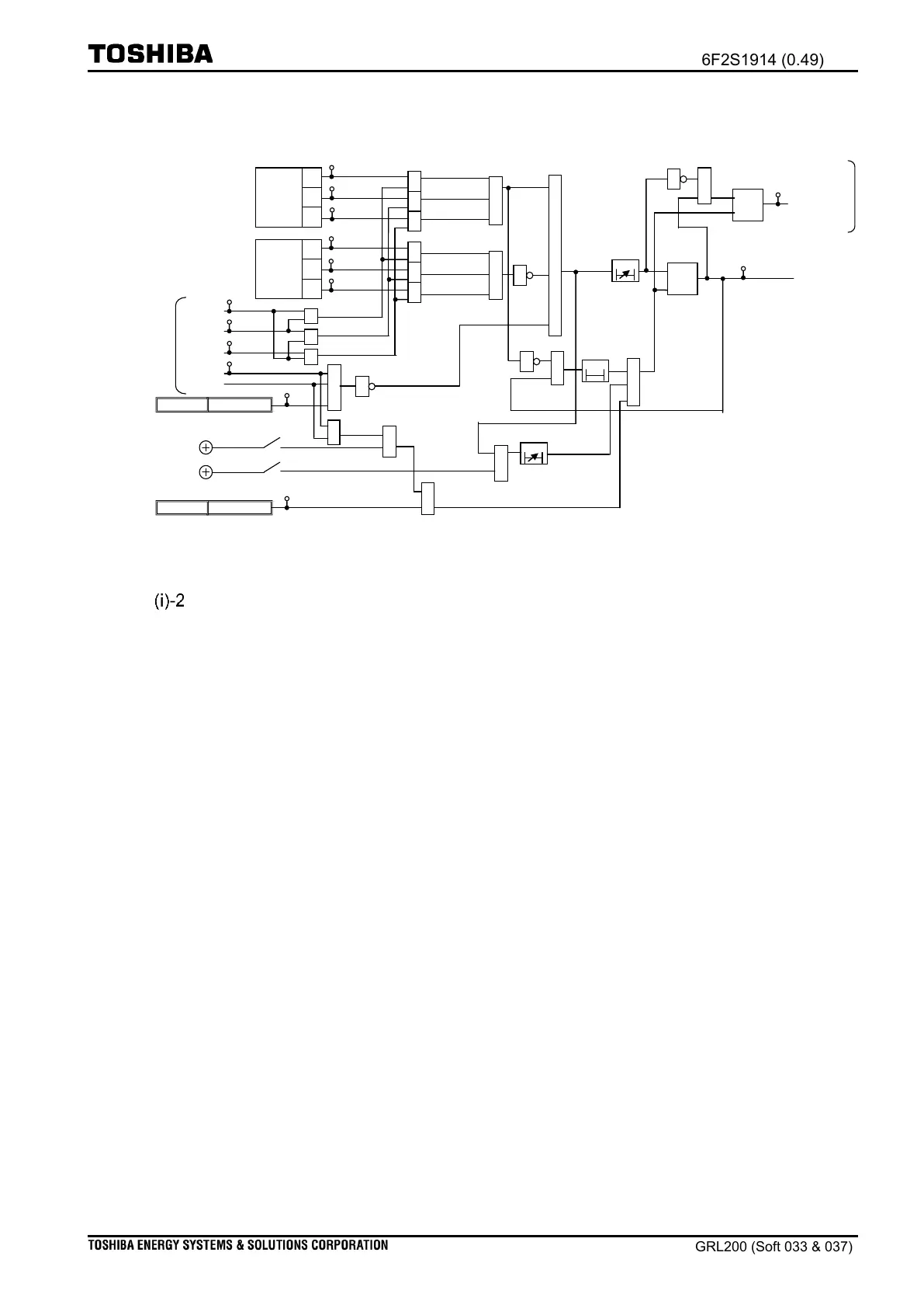
Figure 2.10-29 PSBG logic
Setting for blocking operation of Distance protection
Scheme switches [Z*S-PSBBlk] and [Z*G-PSBBlk] are provided to block the operation of the
respective Z*S and Z*G elements. Generally, it is desirable to block the operation of the
respective ZS elements and ZG elements during a power swing. Thus, Block is set for the
respective scheme switches [Z*S-PSBBlk] and [Z*G-PSBBlk].
However, when it is required to continue the operation of respective ZS and ZG elements
during a power swing, Non is set for respective scheme switches.
(ii) Load encroachment
The load encroachment element is used to improve security when heavy load current flows in
a line. When the impedance remains within the hatched area as shown in Figure 2.10-30, a
signal that reflects the operation of the load encroachment element is yielded; respective ZS
elements are blocked to operate by blocking signals, which can be issued at which Block is set
for the scheme switches [Z*S-LEBlk].
As shown in Figure 2.10-30(a), for ZS the minimum load resistance R is defined by the
setting of scheme switches [LESR] and [LESL]. Setting of the maximum load angles across the
R ordinate is performed using scheme switches [LESR-Angle] and [LESL-Angle].
For ZG, when Block is set for the scheme switches [Z*G-LEBlk], similar settings and
scheme switches are available: settings [LEGR], [LEGL], [LEGR-Angle], and [LEGL-Angle],

 Loading...


